Sensors with thromboresistant coating

a technology of thrombosis and sensors, applied in the direction of instruments, catheters, analysis using chemical indicators, etc., can solve the problems of blood clots or thromboses around the sensor, severe health problems, and impair the functionality of the sensor and/or the health of the patient, so as to reduce the thrombosis of the analyte sensor

Active Publication Date: 2014-05-06
MEDTRONIC MIMIMED INC
View PDF547 Cites 1 Cited by
  • Summary
  • Abstract
  • Description
  • Claims
  • Application Information

AI Technical Summary

Benefits of technology

This patent describes methods for reducing the risk of blood clotting on the surface of an analyte sensor. The methods involve using a solution containing heparin and benzalkonium, or separate solutions containing each substance, to coat the sensor and prevent blood clotting. The sensor is then dried and used for analysis. In addition, a chemical linking agent and an antithrombogenic molecule can be used to further reduce the risk of blood clotting. The linking agent is a compound that forms a strong bond to the sensor's surface, while the antithrombogenic molecule prevents blood clotting. These methods help make the analyte sensor safer and more reliable for use in medical diagnostics.

Problems solved by technology

The presence of foreign bodies in the vascular system of patients, such as intravascular glucose sensors, can lead to the formation of a blood clot or thrombus around the sensor.
In some cases, the thrombus can result in the restriction of blood flow through the blood vessel, impairing functionality of the sensor and / or health of the patient.
In some cases, the thrombus can break off and travel through the bloodstream to other parts of the body, such as the heart or brain, leading to severe health problems.
Unfortunately, depending on the surface material of the device, heparin may not provide a lasting and / or contiguous thromboresistant coating.
However, HBAC has not been used with success for devices, such as intravascular analyte sensors, that require passage of the analyte in the blood through the coating.
Moreover, Hsu (U.S. Pat. No. 5,047,020) disclosed use of various heparin complexes for coating blood gas sensors and noted that the benzalkonium heparin complex was unsuitable for such an intravascular sensor.

Method used


Image

  • Sensors with thromboresistant coating
  • Sensors with thromboresistant coating
  • Sensors with thromboresistant coating

Examples


working examples

Example 1

Application of Thromboresistant Coating

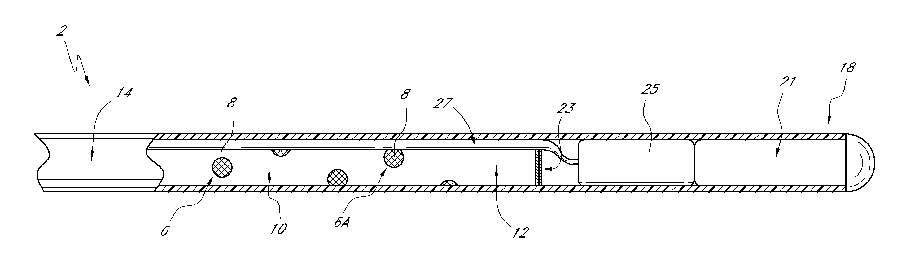
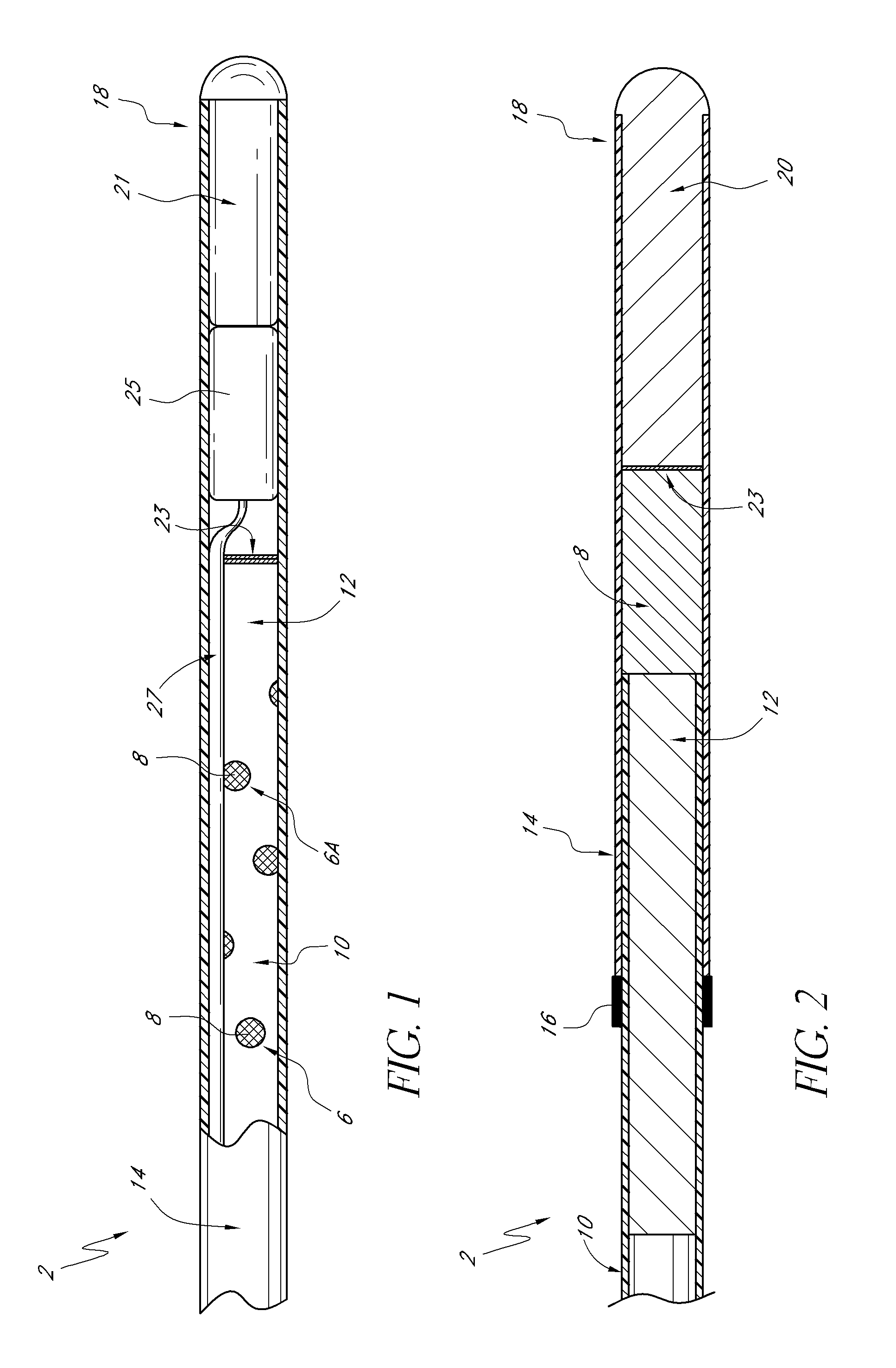
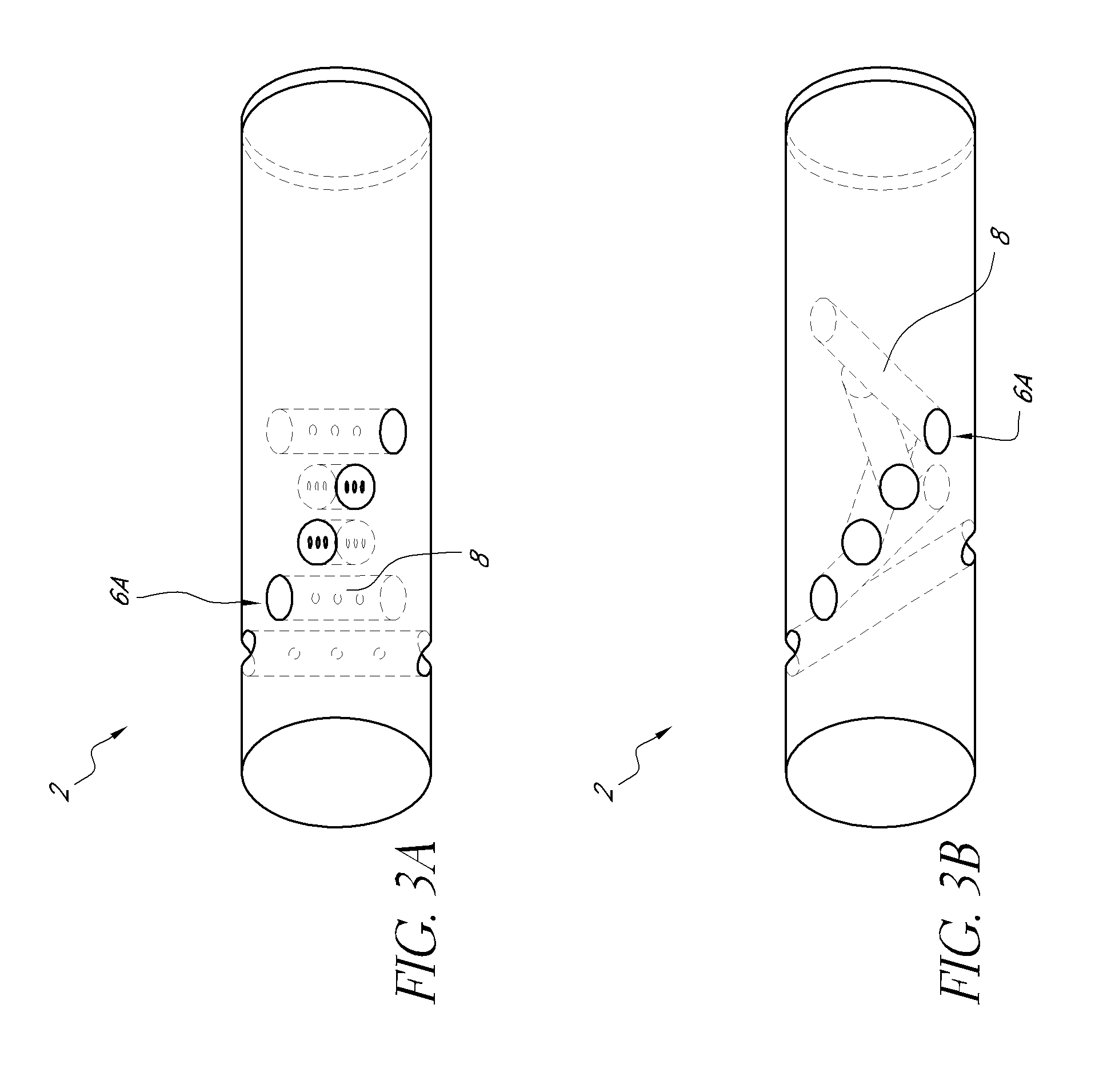
[0140]An optical glucose sensor as described above (see e.g., FIGS. 1-4) was prepared for coating with benzalkonium / heparin by immersing the portion of the sensor to be coated in a pH 3 phosphate buffered saline solution (although it is feasible to use many types of aqueous buffer solutions or even just water).

[0141]A coating solution of 1.5% (by weight) benzalkonium heparin in isopropanol (distributed by Celsus Laboratories, Inc. 12150 Best Place, Cincinnati Ohio 45241 as Benzalkonium heparin solution in isopropyl alcohol, 887 U / mL, Product Number BY-3189) was added to a test tube. After equilibrating in the buffered saline solution, the distal end portion of the sensing end of the sensor was immersed in the benzalkonium heparin solution and immediately removed (with the time of immersion in the benzalkonium heparin solution being approximately one second). The wet sensor was allowed to air dry for approximately 1 minute, resulting in...

example 2

Preparation of Sensor Blank

[0143]A sensor blank was prepared from a polyethylene microporous membrane (of 0.017 inch outside diameter) surrounding a poly(methyl methacrylate) optical fiber (of 0.010 inch diameter). The polyethylene microporous membrane was obtained from Biogeneral 9925 Mesa Rim Road, San Diego Calif. 92121-2911). The distal end of the sensor blank (the end to be coated) is heat welded to a rounded polyethylene plug. The other end is sealed with a silicone backfill. The distal end was then immersed in the buffered saline solution of Example 1 for about 18 hours (although a shorter time interval would also have been suitable). Finally, the distal end of the sensor blank was immersed in the coating solution of Example 1 and subsequently air dried as in Example 1. The steps of immersing in the coating solution and air drying were repeated four times.

example 3

Comparison of Coated Sensor and Coated Sensor Blank

[0144]Coated sensors and coated sensor blanks, prepared as described in Examples 1 and 2, each having five dip coats of heparin / benzalkonium applied, were subjected to handling tests as follows.

[0145]Sensors consisted of a 1.3-inch long hollow, microporous HDPE membrane (0.017 inches O.D., Biogeneral 9925 Mesa Rim Road, San Diego Calif. 92121-2911, this is a custom part) butt-welded to a 1.0-inch long, smooth (nonporous) HDPE tube. The microporous end was heat-welded to a rounded polyethylene plug. Inside of the hollow assembly was threaded a 0.010 inch PMMA optical fiber The smooth HDPE end was filled with silicone backfill up to, but not including, the microporous membrane. The area between the PMMA optical fiber and the hollow microporous membrane was filled with a dimethyl acrylamide gel which also contained covalently-bound fluorescent dye and quencher. The sensor was prepared for application of the coating comprising heparin a...


PUM


Abstract

Embodiments of the present invention relate to analyte sensors comprising a heparin coating, and methods of coating analyte sensors. The heparin can be stably associated with at least a portion of a porous membrane that covers a portion of the analyte sensors. The heparin can be photochemically linked to the coating through the formation of covalent bonds.

Description

INCORPORATION BY REFERENCE TO ANY PRIORITY APPLICATIONS[0001]Any and all applications for which a foreign or domestic priority claim is identified in the Application Data Sheet as filed with the present application are hereby incorporated by reference under 37 CFR 1.57.BACKGROUND OF THE INVENTION[0002]1. Field of the Invention[0003]Embodiments of the present invention generally relate to thromboresistant coatings for medical devices, such as intravascular glucose sensors, having a blood-contacting surface, as well as to methods for forming such coatings, and to the medical devices thus formed.[0004]2. Description of the Related Art[0005]Achieving glycemic control is facilitated by continuous or nearly continuous monitoring of patient blood glucose levels. One method for accomplishing such monitoring is through the use of an implanted glucose sensor. For example, an optical glucose sensor, such as those disclosed in U.S. Pat. Nos. 5,137,033, 5,512,246, 5,503,770, 6,627,177, 7,417,164...

Claims


Application Information

Patent Timeline
Patent Type & Authority Patents(United States)
IPC IPC(8): G01N31/22
CPCG01N21/80G01N2021/773A61B5/14542G01N2021/7786A61B5/1459A61B5/14532A61B5/14539G01N21/7703
Inventor ROMEY, MATTHEW A.GAMSEY, SOYAMARKLE, DAVID R.
Owner MEDTRONIC MIMIMED INC
Why Eureka
Try Eureka