Uninterrupted flow pump apparatus and method

a flow pump and flow-control technology, applied in the direction of positive displacement liquid engine, instrument, and semiconductor/solid-state device details, can solve the problems of biological fluids comprising blood or its cellular components, biological fluids comprising pressure or flow sensitive fluids, and can be negatively affected, so as to reduce total treatment or process time, reduce irradiation time, and increase flow rate

Inactive Publication Date: 2014-05-13
MALLINCKRODT HOSPITAL PRODUCTS IP LTD
View PDF135 Cites 1 Cited by
  • Summary
  • Abstract
  • Description
  • Claims
  • Application Information

AI Technical Summary

Benefits of technology

[0014]Certain of the objects of one or more embodiments of the present invention can, for example, in photopheresis and peritoneal dialysis procedures: reduce total treatment or process time; reduce irradiation time (for photopheresis); allow increased flow rate; increase the total number of target cells collected or separated per total target cells processed (i.e., yield); increase the total number of target cells collected per treatment or process time; increase the total target cells collected per total volume of processed biologic fluid; reduce cell, fluid or fluid element damage in the process (e.g., reduced hemolysis); reduce contamination of target items collected (e.g., increase the percentage of target cells collected per total cells collected); operate with a reduced pressure differential (i.e., reduce the variability of pressure in the system); and, reduce flow rate differential (i.e., reduce the variability of the flow rate in the system).
[0015]An additional object of one or more embodiments of the present invention is to reduce the amount of time that a patient's blood is outside the patient's body.
[0026]Indeed, the method and apparatus of an embodiment of the present invention, in comparison to the known Kamen-type pump technology used in the UVAR® XTS™ photopheresis system manufactured by Therakos, Inc., Exton, Pa., provide for one or more of: a reduction in total treatment or process time for the donor blood in the XTS™ system; a reduction in irradiation time of collected buffy coat in the system; an increased flow rate of whole blood into the system, as well as collected buffy coat out of the centrifuge of the XTS™ system; an increased total number of target cells (e.g., white blood cells) collected or separated per total white blood cells contained in the donor blood (i.e., yield); an increased total number of white blood cells collected per treatment or per unit process time; an increased number of total white blood cells collected per total volume of processed donor blood; a reduction of the contamination of collected white blood cells collected (e.g., an increase the percentage of white blood cells collected per total cells collected and / or decreasing the percent hematocirt in the collected buffy coat); and a reduced pressure differential and a reduced flow rate differential within the extracorporeal circuit.

Problems solved by technology

Certain fluid types, such as fluids comprising pressure or flow sensitive fluids, such as biological fluids, can be negatively affected by subjecting such fluids to such current pumping or delivering methods.
For example, biological fluids comprising blood or its cellular components, may be damaged (e.g., cells may be lysed or membranes damaged) when exposed to perturbations and / or turbulence caused by such current methodologies.
Moreover, these fluid types may also be negatively affected by inaccurate or inconsistent flow rates and pressures created by such current methods.
In addition, drug delivery systems are negatively affected by such inaccurate or inconsistent flow rates.
One of the specific drawbacks, for example, with peristaltic pumps is that they are essentially positive displacement and have the potential to develop excessive pressures if an occlusion occurs within the pump or its components.
When pumping or delivering biological fluids, such as whole blood or buffy coat, any excess pressure resulting from even a partial occlusion may result in cell membrane damage or hemolysis.
Diaphragm pumps present difficulties in the measurement of fluid volume pumped when partial strokes are involved and may require auxiliary valving.
Centrifugal pumps are difficult to track for volume pumped, cannot hold against a static head without check valves, are non-reversible, and generally require some mechanical rotor support in the fluid stream (e.g., a hydrodynamic bearing or magnetic system).
In the drug delivery area, devices such as the hypodermic syringe that deliver a bolus of a drug or other active agent also present difficulties since the bolus must be gradually absorbed and delivered throughout the patient's body, which is a process subject to many individual variances.
These calculations are time consuming and necessarily precise because the stroke volumes are small and the cumulative error must be kept minimal.
In order to maintain the required average flow rate, the actual flow rate must be high, resulting in a step type of flow (a jump up when restarting the flow) which is detrimental, for example, to sensitive fluids in general, to many biological fluids, and to most types of cell separation processes, particularly the “skimming” type cell separation processes commonly used in conjunction with centrifuges.
Additionally, the Kamen family of pump technology requires a rigid disposable pumping or delivering / valving module which contains valve chambers that interrupt the laminar nature of flow in tubing, causing undesired mixing of separated components as the front flows through.
This module (or cassette) is also typically costly and complicated to manufacture.

Method used


Image

  • Uninterrupted flow pump apparatus and method
  • Uninterrupted flow pump apparatus and method
  • Uninterrupted flow pump apparatus and method

Examples


Embodiment Construction

[0039]Reference will now be made in detail to the present preferred embodiments and exemplary embodiments of the invention, examples of which are illustrated in the accompanying drawings.

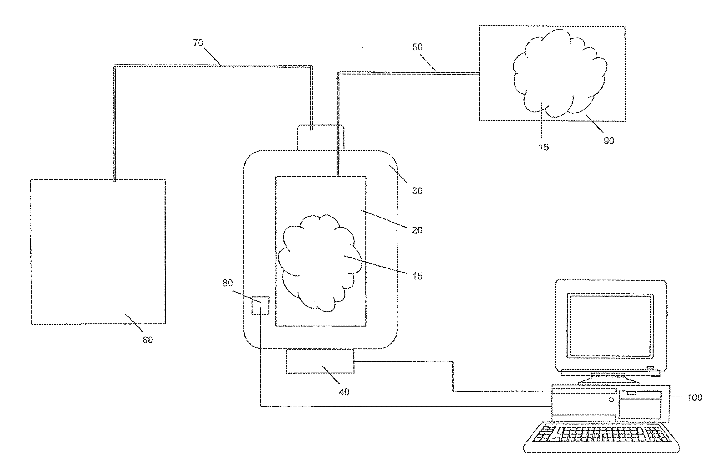
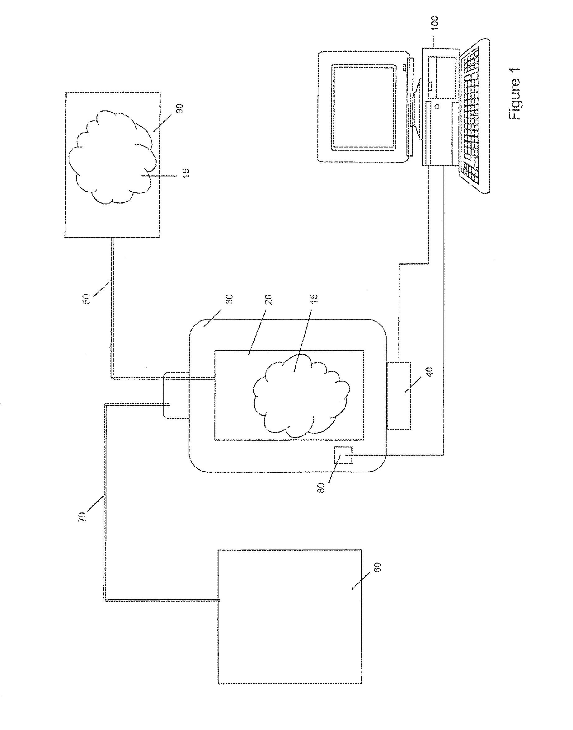
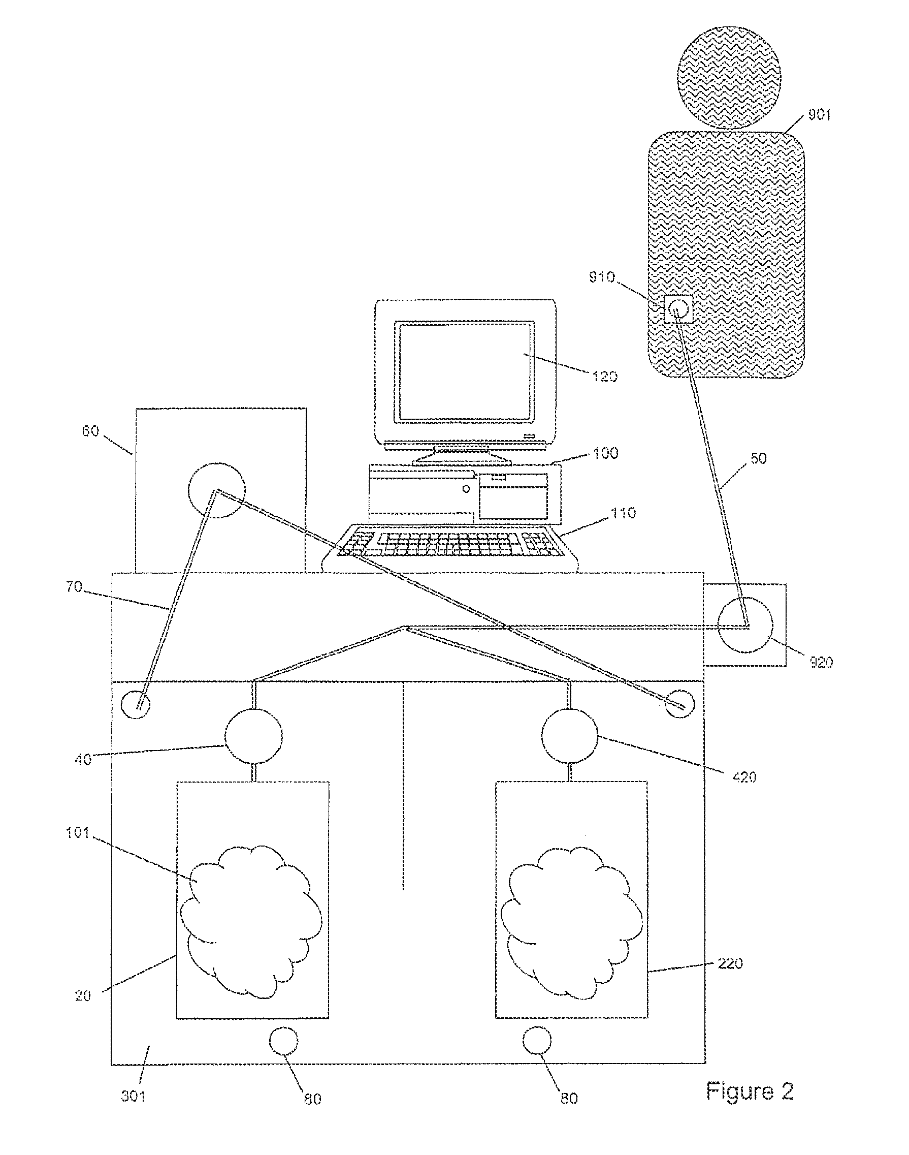
[0040]The present invention apparatus and method for pumping or delivering have a myriad of uses but are most advantageous for use when fluids, particularly biological fluids and pressure sensitive fluids, are pumped and / or when uninterrupted flow of the fluid is preferred. Such applications include biological and medical applications, for example, of photopheresis, cell separation, drug delivery and dialysis. This apparatus and method for pumping or delivering are also useful in providing for the movement of fluids in cyclical systems such as, for example, peritoneal dialysis, bypass and other blood flow processes. The present invention is also useful in other procedures involving the flow of fluids that are sensitive to changes in pressure and discontinuities in flow and has numerous applications ...


PUM


Abstract

This invention describes a method for pumping or delivering fluids utilizing a flexible vessel subject to controlled pressures within another pressure vessel. The pressure vessel can be sourced with positive and / or negative (e.g., vacuum) pressure.

Description

CROSS-REFERENCE TO RELATED APPLICATIONS[0001]The present application is a continuation of U.S. Ser. No. 12 / 427,150 filed Apr. 21, 2009 (now allowed), which is a continuation of U.S. Ser. No. 10 / 290,411, filed Nov. 8, 2002 (now U.S. Pat. No. 7,534,616, issued May 19, 2009), which is a continuation of U.S. Ser. No. 09 / 389,463, filed Sep. 3, 1999 (now U.S. Pat. No. 6,495,366, issued Dec. 17, 2002) the entire disclosures of each of which are hereby incorporated by reference.BACKGROUND OF THE INVENTION[0002]1. Field of the Invention[0003]The present invention relates to a method and apparatus for pumping or delivering fluids utilizing a flexible vessel that may be subject to controlled pressures and preferably located within a pressure vessel.[0004]2. Description of the Prior Art[0005]Current methods for pumping or delivering fluids, particularly biological fluids, include utilizing peristaltic (tubing) pumps, diaphragm pumps, and centrifugal pumps. Biological fluids encompass fluids tha...

Claims


Application Information

Patent Timeline
Patent Type & Authority Patents(United States)
IPC IPC(8): B01L99/00F04B13/00F04B43/00
CPCF17D3/00H01L21/4867H01L23/498H01L2924/0002H05K1/111H05K3/225H05K3/321H05K3/3463H05K2201/0257H05K2201/0373H05K2201/10628H05K2203/176Y10T436/25Y10T436/2575Y10T137/0396H01L2924/00
Inventor BRIGGS, DENNIS A.
Owner MALLINCKRODT HOSPITAL PRODUCTS IP LTD
Why Eureka
Try Eureka