Surface acoustic wave device, electronic apparatus, and sensor apparatus

a surface acoustic wave and electronic equipment technology, applied in the direction of device material selection, generator/motor, impedence network, etc., can solve the problems of product reliability and quality damage, difficulty in reducing size and high q value, and unsatisfactory reflection efficiency of the saw by the reflector, etc., to improve the q value, improve the ci value, and small frequency fluctuation

Inactive Publication Date: 2014-05-13
SEIKO EPSON CORP
View PDF70 Cites 4 Cited by
  • Summary
  • Abstract
  • Description
  • Claims
  • Application Information

AI Technical Summary

Benefits of technology

[0022]The invention is made by considering the above-described problems, and the object thereof is to provide a SAW device, such as a resonator or an oscillator, capable of exhibiting an excellent frequency-temperature characteristic with a very small frequency fluctuation in an operation temperature range, having an excellent environment-resistant characteristic ensuring a stable operation even in an environment in which a temperature varies extremely, and realizing a high Q value.

Problems solved by technology

Thus, the reflection efficiency of the SAW by the reflector is unsatisfactory compared to an ST cut quartz crystal SAW device in which a SAW propagates along the substrate surface, making it difficult to realize reduction in size and a high Q value.
As a result, if a variation occurs in the frequency fluctuation with a change in the temperature of the SAW device, product reliability and quality are damaged.
When the frequency-temperature characteristic of the SAW device is a quadratic curve in the operation temperature range, it is difficult to realize minimization of a frequency fluctuation range or an inflection point.

Method used


Image

  • Surface acoustic wave device, electronic apparatus, and sensor apparatus
  • Surface acoustic wave device, electronic apparatus, and sensor apparatus
  • Surface acoustic wave device, electronic apparatus, and sensor apparatus

Examples


Embodiment Construction

[0102]Hereinafter, preferred examples of the invention will be described in detail with reference to the accompanying drawings. In the accompanying drawings, the same or similar constituent elements are represented by the same or similar reference numerals.

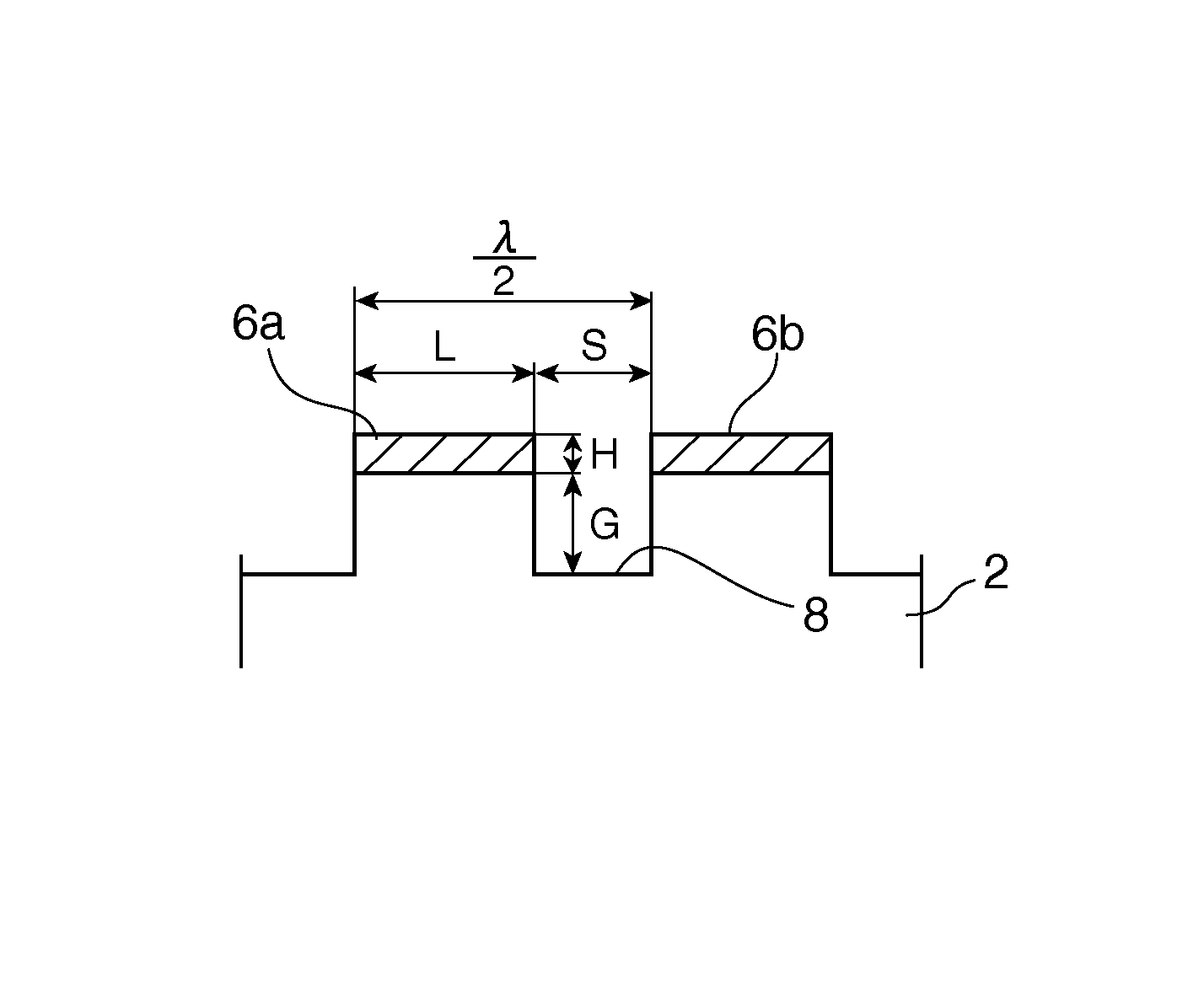
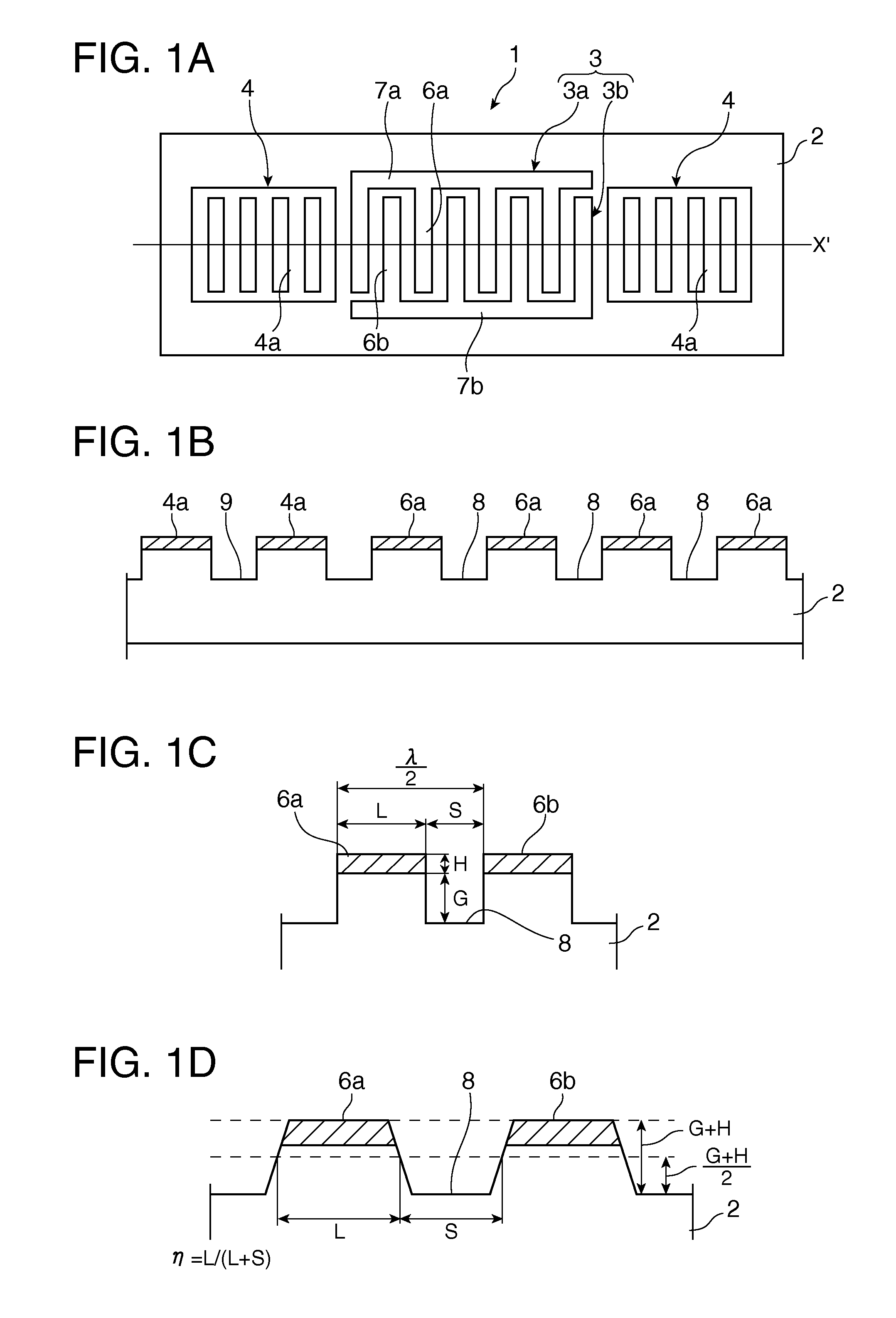
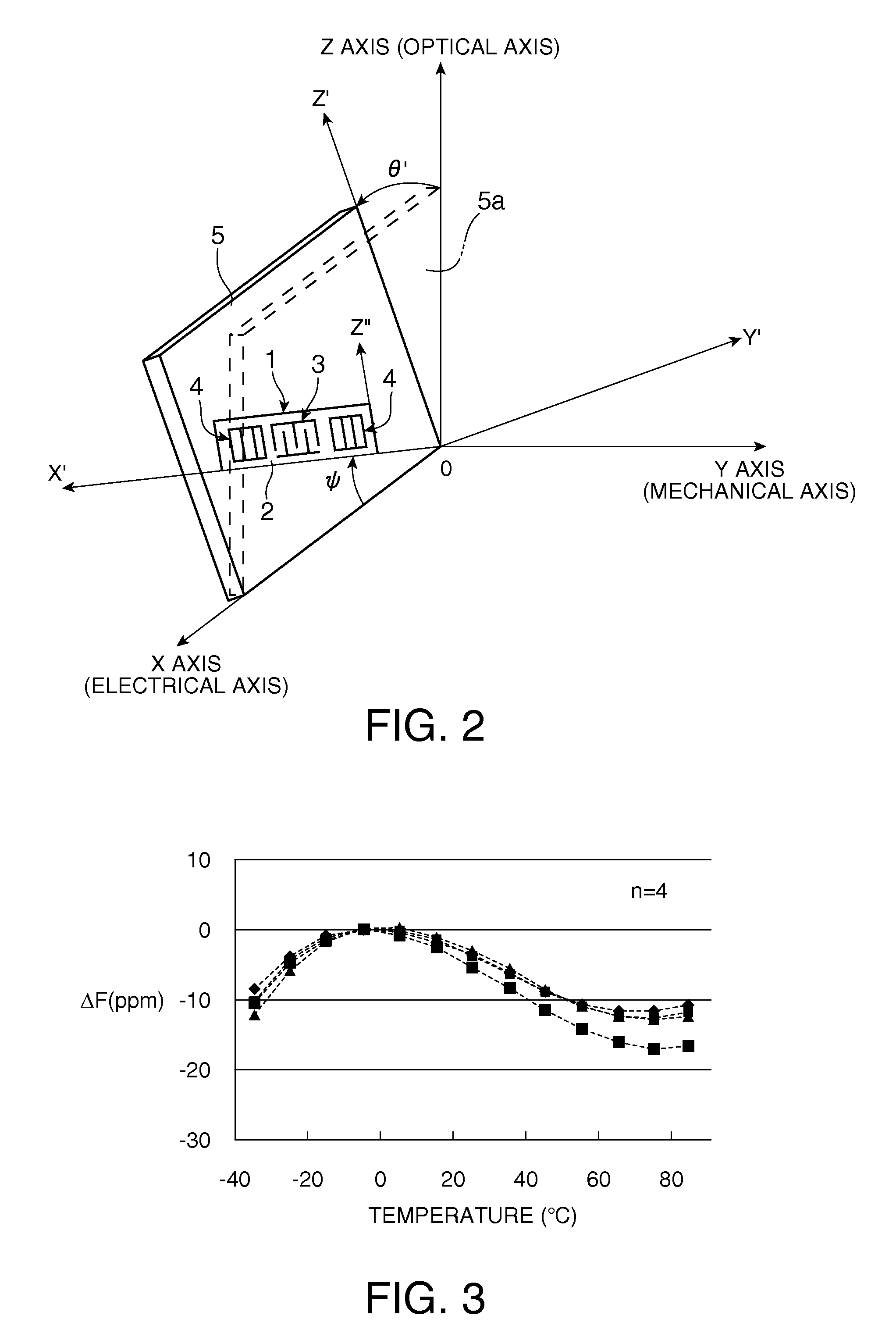
[0103]A SAW resonator which is a first example of a SAW device according to the invention has the same basic configuration as the SAW resonator 1 shown in FIG. 1, and description thereof will be provided with reference to FIG. 1. That is, the SAW resonator 1 of this example has a rectangular quartz crystal substrate 2, and an IDT 3 and a pair of reflectors 4 and 4 which are formed on the principal surface of the quartz crystal substrate. The quartz crystal substrate 2 uses a quartz crystal substrate having Euler angles (−1.5°≦φ≦1.5°, 117°≦θ≦142°, ψ). The Euler angle ψ is set such that |ψ|≠90°×n (where n=0, 1, 2, 3) is satisfied.

[0104]The IDT 3 has a pair of interdigital transducers 3a and 3b which respectively have a plurality of ...


PUM


Abstract

A SAW device has an IDT which is provided in the principal surface of a quartz crystal substrate having Euler angles (−1.5°≦φ≦1.5°, 117°≦θ≦142°, |ψ|≠90°×n (where n=0, 1, 2, 3)) and excites a Rayleigh wave (wavelength: λ) in a stopband upper end mode. Inter-electrode-finger grooves are recessed between the electrode fingers of the IDT. The depth G of the inter-electrode-finger grooves is 0.01λ≦G≦0.07λ, and an electrode finger thickness H and an IDT line occupancy η satisfy a predetermined relationship. Thus, a frequency-temperature characteristic constantly has an inflection point between a maximum value and a minimum value in an operation temperature range, thereby suppressing a fluctuation in an inflection-point temperature due to a manufacturing variation in the IDT line occupancy η.

Description

TECHNICAL FIELD[0001]The present invention relates to a surface acoustic wave device, such as a resonator or an oscillator using a surface acoustic wave (SAW), and an electronic apparatus and a sensor apparatus including the same.RELATED ART[0002]SAW devices are widely used in electronic apparatuses, such as a mobile phone, a hard disk, a personal computer, a receiver tuner of BS and CS broadcasts, an apparatus which processes a high-frequency signal or an optical signal propagating through a coaxial cable or an optical cable, a server network apparatus which requires a high-frequency and high-precision clock (low jitter and low phase noise) in a wide temperature range, and a wireless communication apparatus, or various sensor apparatuses, such as a pressure sensor, an acceleration sensor, and a rotational speed sensor. In these apparatuses and devices, in particular, with the realization of a high-frequency reference clock due to recent high-speed performance of information communi...

Claims


Application Information

Patent Timeline
Patent Type & Authority Patents(United States)
IPC IPC(8): H03H9/25H01L41/09H01L41/18H01L41/22H01L41/311H03B5/30H03H9/145
CPCH03H9/02661H03H9/02551H03H9/02834H03H9/14538
Inventor OBATA, NAOHISAYAMANAKA, KUNIHITO
Owner SEIKO EPSON CORP
Why Eureka
Try Eureka