Liquid barrier and method for making a liquid barrier

Active Publication Date: 2014-05-27
R S M ELECTRON POWER
View PDF6 Cites 2 Cited by
  • Summary
  • Abstract
  • Description
  • Claims
  • Application Information

AI Technical Summary

Benefits of technology

[0010]One aspect of the invention is that it provides a liquid barrier compatible with manufacturing processes associated with power electronics components and substrates. Another aspect of the invention is that a liquid barrier can withstand repeated thermal stress during typical device packaging processes as well as during high-temperature operation and storage of a packaged device. Yet another aspect of the invention is that a liquid barrier, when formed on a substrate and used during the manufacturing process of a device, provides a contact angle differential between areas in which liquid flow is desired and areas in which it is not.

Problems solved by technology
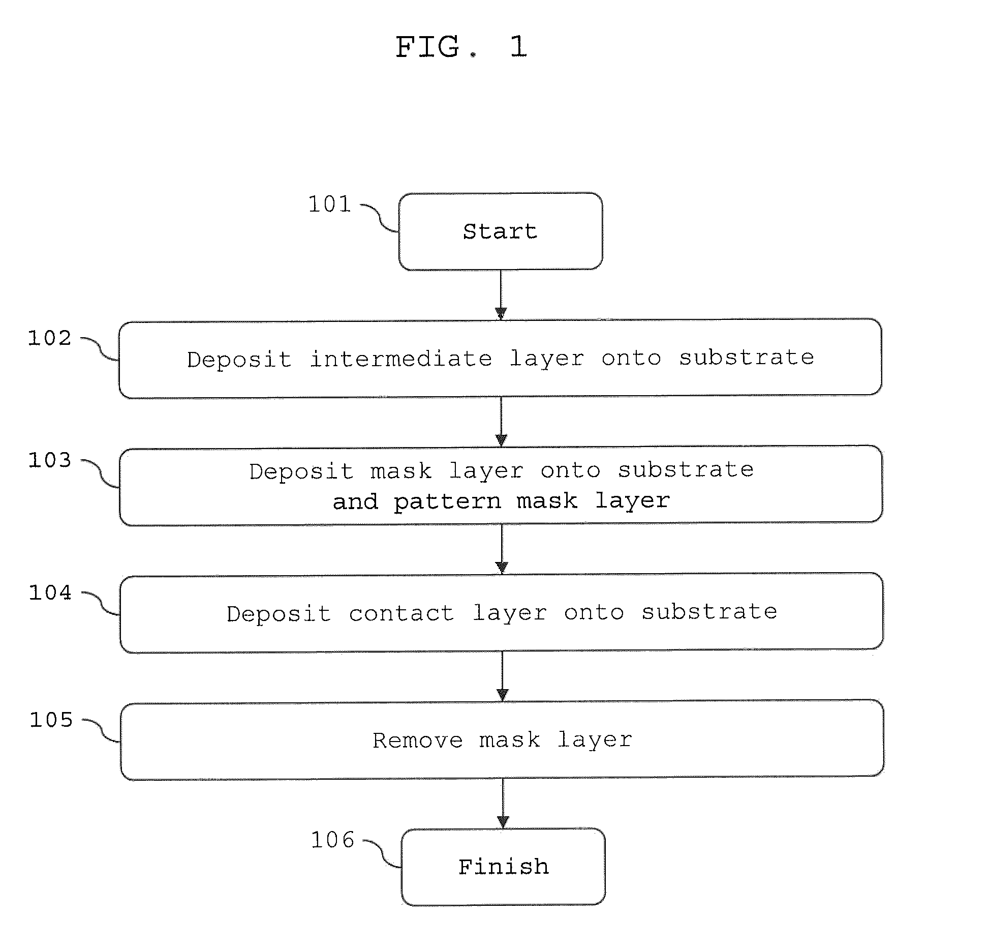
In some embodiments, liquid barriers can be formed by selectively plating or depositing material layers onto a substrate such that some areas of the substrate possess high contact angles with respect to a liquid, and thus do not readily wet the liquid, while other areas possess low contact angles and are susceptible to flow of the liquid.

Method used


Image

  • Liquid barrier and method for making a liquid barrier
  • Liquid barrier and method for making a liquid barrier
  • Liquid barrier and method for making a liquid barrier

Examples


Embodiment Construction

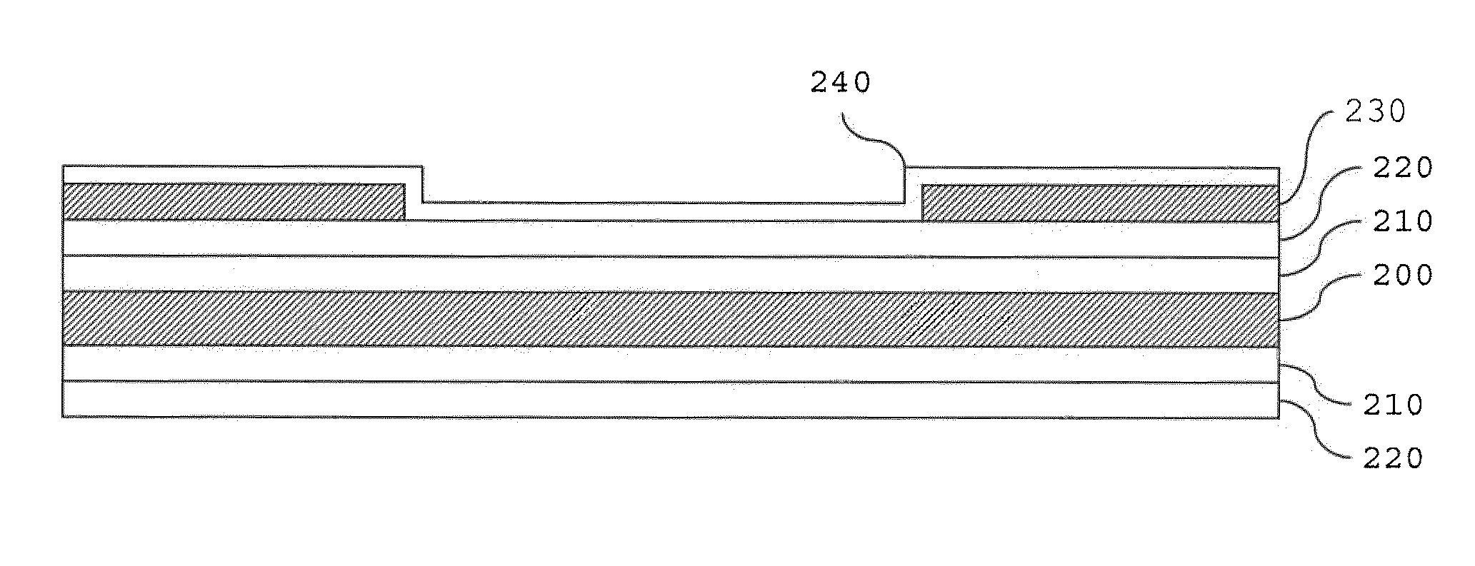
[0019]As noted above, one aspect of the invention is that a liquid barrier can be formed by creating a contact angle differential between surfaces in which liquid flow is desired and areas in which it is not. In other words, a boundary between areas of sufficiently different wettabilities can provide a barrier to the flow of a liquid. A highly wetting area, i.e., one with a low contact angle, is an area where liquid flow is intended or desired; a bordering area with low wettability, i.e., an area with a high contact angle, is one where liquid flow is prevented. The boundary between these areas is thus a liquid barrier because it can impede the flow of a liquid from the low contact angle area on to the high contact angle area, hence controlling and confining the liquid to stay within the low contact angle area.

[0020]The extent to which a liquid wets or spreads on a surface depends upon the interfacial energies between the liquid, the surface, and the ambient. At steady state, thermod...


PUM

PropertyMeasurementUnit
contact angleaaaaaaaaaa

Abstract

A method for making a liquid barrier includes forming a liquid barrier layer on a substrate, forming a mask layer on the liquid barrier layer such that part of the liquid barrier remains exposed, forming a contact layer on the exposed liquid barrier layer, and removing the mask layer to expose the part of the liquid barrier layer which was covered by the mask layer. A liquid wetting boundary is formed when the wettability on the liquid barrier surface area is less than the wettability of the contact surface area.

Description

BACKGROUND OF THE INVENTION[0001]1. Field of the Invention[0002]Example aspects of the invention relate generally to the manufacturing of electronics products, and, more specifically, to the processing of electronics components where liquid flow control and containment is required.[0003]2. Description of the Related Art[0004]Packaging for power electronics can require the use of metallized substrates that provide electrical isolation between components yet maintain high electrical and thermal conductivity. Such components, which include diodes, metal oxide semiconductor field-effect transistors (MOSFETs), insulated-gate bipolar transistors (IGBTs), resistors, and capacitors, are typically attached to substrates using solder alloys. During the attachment process, however, the flow of solder must be controlled to achieve the necessary electrical isolation between components and to maintain the proper orientation and alignment of the components. A known practice is to apply a polymer o...

Claims


Application Information

Patent Timeline
Patent Type & Authority Patents(United States)
IPC IPC(8): H01B13/00
CPCC04B2237/125H01L21/4853C04B2237/368C04B2237/366C04B2237/365C04B2237/12C04B2237/86C04B2237/343H01L2924/0002C04B2237/72H01L23/3735C04B37/006C04B2237/123C04B2237/34H01L23/49811
Inventor AU, CHINGKALYANASUNDARAM, KRITHIKA
Owner R S M ELECTRON POWER
Why Eureka
Try Eureka