Blow-molded plastic infusion container

a plastic infusion container and blow molding technology, which is applied in the direction of containers preventing decay, packaging foodstuffs, and packaged goods, etc., can solve the problems of inflexibility, excessive amount of drug solution to remain in the container, and the method of insertion of air needles into the rubber stopper of the container has a disadvantage for working, so as to reduce the amount of residual liquid, easy to fold, and easy to fold

Inactive Publication Date: 2014-10-21
NIPRO CORP
View PDF6 Cites 26 Cited by
  • Summary
  • Abstract
  • Description
  • Claims
  • Application Information

AI Technical Summary

Benefits of technology

[0017]According to the present invention, the following advantageous effects are produced: Since the infusion container of the present invention is so blow-molded that a barrel has a pair of wide sidewalls and a pair of narrow sidewalls, the narrow sidewalls are made into a thin-walled section as compared with other parts, and thus the barrel is apt to be flattened in the direction of the short axis of the barrel. Further, since the bottom is formed into a V-shape bent inwardly and symmetrically with respect to the long axis of the bottom, i.e., since the external side of the bottom is formed by blow-molding so as to be concaved longitudinally like a V-shaped groove, the curved sections between the wide sidewalls and V-shaped portions are made relatively thin, allowing the inner wall surfaces of the wide sidewalls and the inner wall surfaces of the V-shaped portions to come into closely contact with one another by discharge of the liquid, resulting in almost no residual liquid in the bottom of the container.
[0018]Further, the shoulder has a pair of wide sidewalls and a pair of narrow sidewalls, of which the narrow sidewalls may be provided with groove portions of a V-shape bent inwardly and symmetrically with respect to the long axis of the bottom. In this case, curved portions between the narrow sidewalls of the shoulder and the grooves are relatively made thin as compared with other portions, allowing the inner wall surfaces of the wide sidewalls and the V-shaped portions to come into contact with one another by discharging the liquid, thereby considerably reducing the amount of the residual liquid in the shoulder. In addition, when the bottom and the shoulder are provided in the curved portions thereof with fold lines, they become more easily foldable in the short axis direction. Further, when the barrel is provided in the narrow sidewalls thereof with fold lines foldable outward and symmetric to the longitudinal axis, it becomes more easily foldable in the short axis direction. When the whole container is apt to be foldable under pressure, it is possible to decrease the volume of the containers at the time of throwing out the containers, thus making it possible to reduce the costs incurred during waste disposal.
[0019]In the conventional bottle, the amount of air to be injected into the bottle for removal of the residual liquid is determined by a volume of unfolded portions of the bottle under the flattened conditions of the bottle. In contrast therewith, the infusion container of the present invention makes it possible to considerably reduce the amount of air to be injected as compared with the conventional containers. Because, the infusion container of the present invention has a bottom with a configuration of a V-shape bent inwardly and symmetrically with respect to the long axis of the bottom, and a shoulder with V-shaped grooves, allowing the wide sidewalls of both the barrel and shoulder to respectively move toward the V-shaped wall of the bottom and the V-shaped grooves of the shoulder at the time of discharge of the solution, resulting in almost no space between the wide sidewalls and the V-shaped wall of the bottom and between the wide sidewalls and the V-shaped grooves of the shoulder.
[0020]Additionally, the V-shaped grooves formed in the shoulder are allowed to telescope into a part adjacent to the scarcely foldable neck to fill the aforesaid adjacent part that may create a dead space, thus making it possible to reduce the injection volume of air by just that much.
[0021]In case that the bottom is so designed as to have a grounding portion with edge lines linearized in the direction parallel to the long axis of the bottom, the edge portions of the grounding portion which become folds are subjected to stresses in the same direction, resulting in improvement in flexibility of the edge portions. As a result, the bottom is further reduced in the dead space, resulting in almost no residual liquid in the bottom even after sterilization.

Problems solved by technology

However, such bottle type infusion containers are formed by blow-molding, causing problems in flexibility.
Thus, the blow-molded containers can not be sufficiently flattened under pressure by the discharge of the drug solution, causing excessive amounts of the drug solution to remain in the container.
However, the method of insertion of the air needle into the rubber stopper of the container has a disadvantage for working since it takes a lot of trouble for insertion of the air needle and since it requires extreme care to prevent it from being contaminated by harmful bacteria.
Further, the method of increasing the content of the gas such as air in the container is disadvantageous in that the container increases in size with reserving the space for air to be charged therein.
In addition, the method, when performed by the use of an infusion pump, necessitates additional human hands and devices since it is necessary to monitor and prevent the introduction of excess air into the blood vessel of the patient because of a fluid level sensor failure.
However, such bag type containers have a disadvantage for performing the infusion since they can not be held upright because of the material and shape of the container.
However, the infusion container of patent document 1 possesses insufficient flattening of the shoulder and bottom, and thus there is dissatisfaction with a large amount of air to be injected.
The infusion container of patent document 2 has been somewhat improved in flattening property, but it is insufficient in flattening of the shoulder and bottom, in particular, flattening of the shoulder, which therefore causes dissatisfaction because of a large amount of air to be injected.Patent document 1: JP, H06-000114YPatent document 2: JP, P2002-282335A

Method used


Image

  • Blow-molded plastic infusion container
  • Blow-molded plastic infusion container
  • Blow-molded plastic infusion container

Examples


example 1

[0075]Firstly, example 1 of the present invention will be explained with reference to FIG. 1 to FIG. 5.

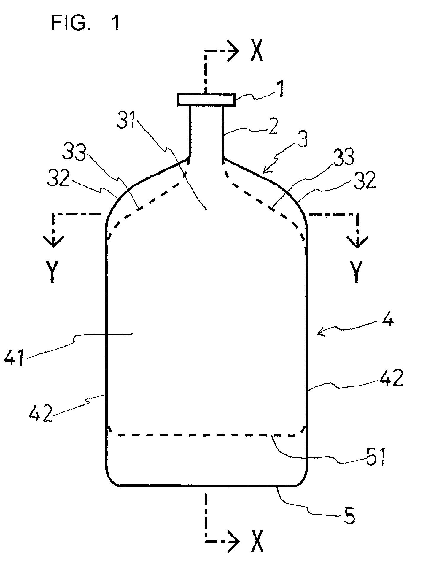
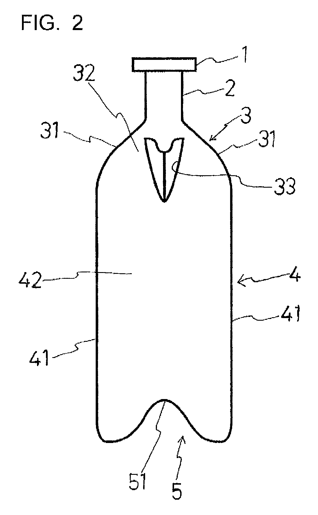
[0076]FIG. 1 is a front view of an infusion container illustrating example 1 of the present invention; FIG. 2 is a side view of the container shown in FIG. 1; FIG. 3 is a plan view of the container shown in FIG. 1; FIG. 4 is a cross-section view of the container taken along the line X-X in FIG. 1; FIG. 5 is a cross-section view of the container taken along the line Y-Y in FIG. 1.

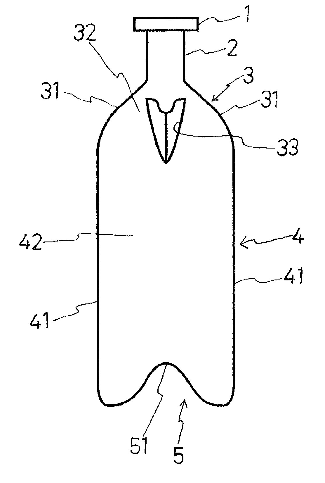
[0077]As shown in FIGS. 1-5, the infusion container of example 1 is a blow-molded container having a mouth 1, a neck 2, a shoulder 3, a barrel 4 and a bottom 5. The barrel 4 has a pair of wide sidewalls 41, 41 and a pair of narrow sidewalls 42, 42. The bottom 5 is formed into a V-shape bent inwardly and symmetrically with respect to the long axis of the bottom. The shoulder 3 also has a pair of wide sidewalls 31, 31 and a pair of narrow sidewalls 32, 32, of which the narrow sidewalls 32, 32 are respectively...

example 2

[0081]Secondly, the present invention will be explained on example 2 with reference to FIG. 6 to FIG. 10.

[0082]FIG. 6 is a front view of an infusion container according to example 2 of the present invention; FIG. 7 is a side view of the container shown in FIG. 6; FIG. 8 is a plan view of the container shown in FIG. 6; FIG. 9 is a cross-section view of the container along the line X-X in FIG. 6; and FIG. 10 is a cross-section view of the container along the line Y-Y in FIG. 6.

[0083]As shown in FIGS. 6-10, the infusion container of example 2 is a container having a mouth 1, a neck 2, a shoulder 3, a barrel 4 and a bottom 5. The barrel 4 has a pair of wide sidewalls 41, 41 and a pair of narrow sidewalls 42, 42. The bottom 5 is formed into a V-shape which is bent inwardly and symmetrically with respect to the long axis of the bottom 5. Also, the shoulder 3 has a pair of wide sidewalls 31, 31 and a pair of narrow sidewalls 32, 32, among which the narrow sidewalls 32, 32 of the shoulder 3...

experiment 6

[0097]In example 5, the containers were formed into a configuration shown in FIGS. 17 and 18 and having a weight of 14.7 g and a capacity increased by 50 mL compared to the container of example 5. For each of the containers, a residual volume was measured in the same manner as in example 5 before and after sterilization. Results are shown in Table 3. The bottles of example 6 showed good results since the container even after being sterilized has the residual volume of 22 mL which is not more than half of the bottle of comparative example 1.


PUM


Abstract

A bottle-type blow-molded plastic infusion container that can be set in an upright position. When liquid is discharged from the container, almost no dead space occurs in shoulder and bottom portions (required amount of air to be placed in the container to remove residual liquid is less). The blow-molded container has a mouth section (1), a neck section (2), the shoulder section (3), a barrel section (4), and the bottom section (5). The barrel section (4) has a pair of broad side faces (41, 41) and a pair of narrow side faces (42, 42). The bottom section (5) is formed in a shape symmetrical about a longitudinal axis of the bottom section (5) and bent inward in a V shape. Further, the shoulder section (3) has a pair of broad side faces (31, 31) and a pair of narrow side faces (32, 32). In the narrow side faces (32, 32) are formed grooves (33, 33) symmetrical about a longitudinal axis and bent inward in a V shape.

Description

TECHNICAL FIELD[0001]The present invention relates to a blow-molded plastic infusion container for storing an infusion solution or dextrose solution for use in intravenous drip therapy or the like.BACKGROUND ART[0002]There are what are known as the plastic infusion containers; a bag type made of a plastic sheet and a bottle type produced by blow-molding.[0003]The bottle type infusion containers have the advantage of being able to stand upright. However, such bottle type infusion containers are formed by blow-molding, causing problems in flexibility. Thus, the blow-molded containers can not be sufficiently flattened under pressure by the discharge of the drug solution, causing excessive amounts of the drug solution to remain in the container. For this reason, some measures taken in the prior art are those such as, for example, a method of inserting an air needle into a rubber stopper of the container, in which the inside and the outside of the container are fluid-communicated with ea...

Claims


Application Information

Patent Timeline
Patent Type & Authority Patents(United States)
IPC IPC(8): A61J1/05B65D25/10B65D6/00A61B19/00B65D23/00B65D1/02
CPCB65D1/0261A61J1/05B65D23/003B65D1/0292B65D1/02
Inventor SANO, YOSHIHIKOFUTAGAWA, HITOSHIKIKUCHI, TOSHIHIRO
Owner NIPRO CORP
Why Eureka
Try Eureka