

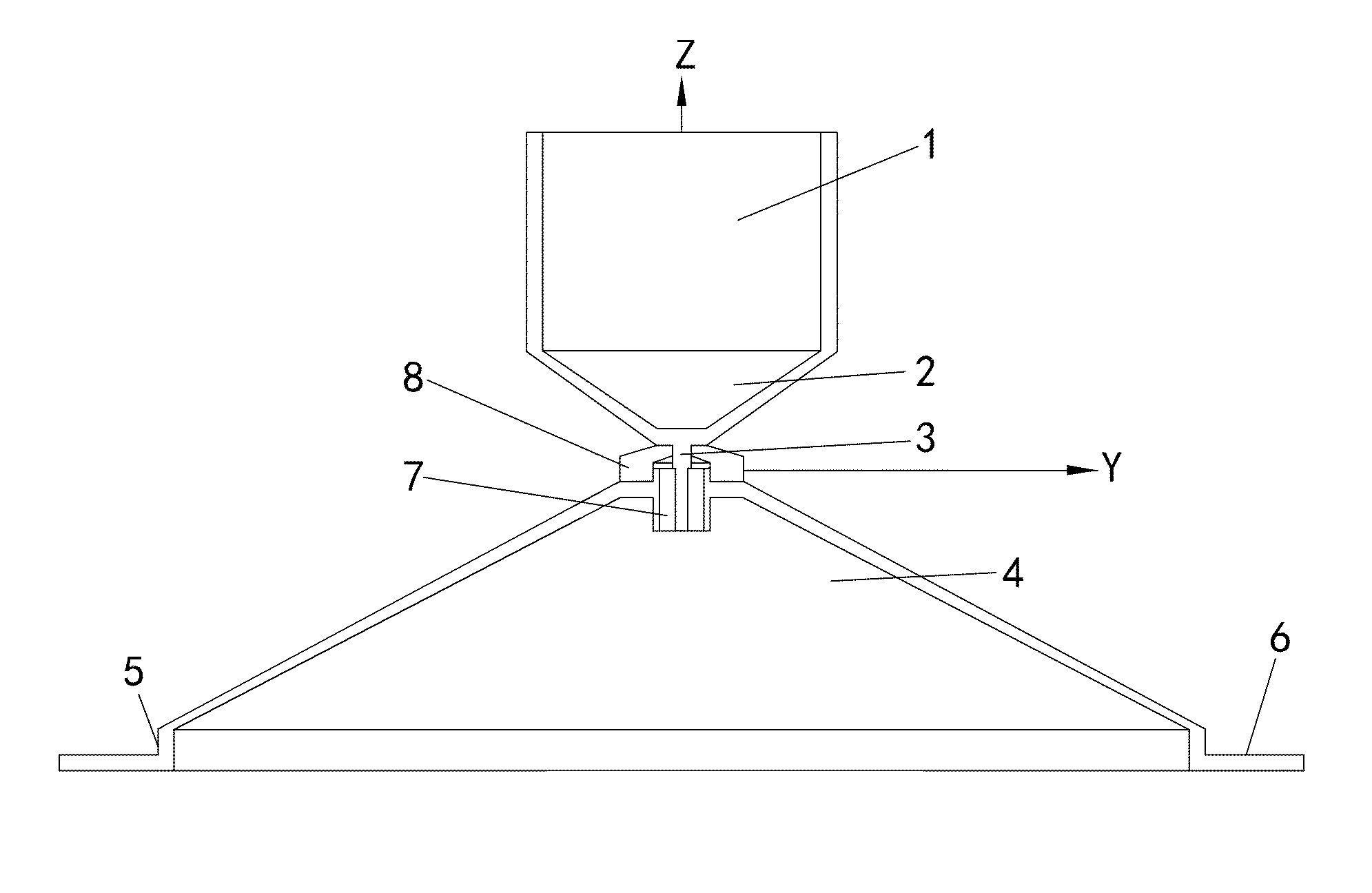
Indoor ceiling-mount omnidirectional antenna and a method for manufacturing the same
a ceiling-mount, omnidirectional antenna technology, applied in the field of mobile communication, can solve the problems of system focus right under the antenna excessively, double-cone structure, and rapid attenuation of gain with the increase of radiation angle, so as to promote efficiency, uniform and stable signal distribution, and improve coverage range.
- Summary
- Abstract
- Description
- Claims
- Application Information
AI Technical Summary
Benefits of technology
Problems solved by technology
Method used
Image

Examples
Embodiment Construction
[0047]With the attached diagrams, a detailed description for the present invention as following.
[0048]On the defects of existing ceiling omnidirectional antennas that focusing signal within small radiating angle in signal in high frequency band excessively and unevenly signal distribution, and give consideration of uniformity of the gain and the direction in high and low frequency bands, a high performance ceiling-mount omnidirectional antenna for indoor distribution system is designed that ensures performance in low frequency band and to improve it in high frequency band. Specifically, the gain in high frequency band decreases at a low radiating angle and increases at a high radiating angle. Meanwhile, considering that grounding and lightening protection of dipole for indoor antenna have little practical significance, in order to improve the un-roundness, the lightening protection and grounding sheet(s) is cancelled and the volume of the antenna is reasonably enlarged. By exact des...
PUM
| Property | Measurement | Unit |
|---|---|---|
| radiating angles | aaaaa | aaaaa |
| wavelength | aaaaa | aaaaa |
| radiating angle | aaaaa | aaaaa |
Abstract
Description
Claims
Application Information