Distance-dependent spectra with uniform sampling spectrometry

a technology of distance-dependent spectra and uniform sampling spectrometry, which is applied in direction finders using radio waves, pulse characteristics measurements, instruments, etc., can solve the problems of inability to improve the spread-spectrum coding bound, limited single link or cellular scenario, and inability to enable general use of physical space. to achieve the effect of enhancing the observability of scaled spectra

Inactive Publication Date: 2014-12-02
GURUPRASAD VENKATA
View PDF10 Cites 6 Cited by
  • Summary
  • Abstract
  • Description
  • Claims
  • Application Information

AI Technical Summary

Benefits of technology

[0029]Accordingly, the primary object of the present invention is to provide very general methods for obtaining distance-dependent frequency scaling without nonuniform sampling and without having to vary grating intervals. A second object is to enable more flexible and robust realizations of the distance-dependent frequency scaling operator avoiding problems of custom design and blurring, and in a form suitable for incorporation downstream from antennae or optical frontends, as well as in correlation spectroscopy. A further object is to provide a fundamental alternative to varying of grating or sampling intervals so as to complete the theoretic picture, and thus make distance-dependent frequency scaling a reliable foundation for future communication technology.
[0036]Equation (11) says that an exponential variation of the diffracted path refractive index will have the same distance-dependent spectral scaling effect as the variation of grating intervals in the first copending application. The basic advantage is that the grating intervals do not need to be physically varied, so that a conventional diffraction grating can be employed. The spatial uniformity of the intervals is assured so that the distance-dependent scaling of the spectrum can be obtained without blur due to nonuniformities in the grating.B. Inventive Principle for Digital Systems
[0049]The advantages are the elimination of sample interpolation and its associated noise, and capability for use without interpolation downstream from the antenna frontend, including at intermediate frequencies wherein the path phase differences would be smaller than at the frontend carrier frequencies and could be otherwise lost in the interpolation noise. The time-domain waveform, with chirp characteristics, can be reconstructed from by a conventional (unmodified) inverse DFT (second of equations 12).C. Inventive Principle for Correlation Spectroscopy
[0059]A more mundane variant, suitable with a photodetector instead of visual observation of the spectrum, is to use a lens of variable focal length and to physically move the photodetector and the lens longitudinally while simultaneously adjusting the focal length so as to achieve the same path length variation. The advantage would be that no material medium of variable optical properties is then necessary; this could be useful for avoiding absorption and scattering noise from the material media, as well as constraints on the polarization. The only robust variable focal length optics available today is the telescoping zoom lens commonly found on cameras, and the speed of mechanical motion would as such limit the β realizable. More options will likely become available from emerging technologies like “smart materials”.
[0063]Further, the variation of the lags or path delays can be repeated over successive observation intervals, so as to enhance the observability of the scaled spectra, as described in the first copending application for the alternative inventive methods described therein. The repetition can be performed by resetting the refractive index, or the lags or delays, before each successive interval. The same result can also be achieved by reversing the sign of β between alternate intervals.

Problems solved by technology

Spread-spectrum coding cannot improve this bound because it concerns modulation within the channel, redistributing the use of the spectrum rather than introducing a new dimension.
Small antenna arrays are being researched for similarly improving link bandwidths, and this is somewhat inappropriately termed space division multiplexing by some authors, in view of the larger antenna cross-sections and multiplexing of the directional patterns of the antenna elements, albeit only within the point-to-point link and between the link end points.
The prior ideas of using the spatial dimensions for multiplexing thus have been limited to single link or cellular scenarios.
They did not enable general use of physical space as a multiplexing dimension that in principle would have permitted discrimination and selection of signals from an unlimited number of sources, and might have obviated time or frequency division, and the base stations networks currently needed for cellular localization of channel allocations.
Prior Methods and their Difficulties.
As such these mechanisms would have to be incorporated in the frontend antennae or optical subsystems, which are generally difficult to access and would entail custom design.
Correctness of inversion is also unobvious because of the reinterpolation, and its empirical verification would always be incomplete as it is physically impossible to test with all possible input signals.
There are also practical problems with interpolating samples, namely that every stage of interpolation adds noise due to its finite order and precision.
Interpolating samples quantized at 3 or 9 levels, as in radio telescopes including the Arecibo, could render the data too noisy.
Moreover, much ongoing work in radio astronomy concerns the power spectrum at 100 GHz and above, for which the conventional ADC-DFT scheme becomes quite impractical.
The basic difficulty for a fundamental alternative is the requirement that the receiver variation cannot be equivalent to any static nonuniform pattern.
Such a grating could be spun on a transverse axis, so as to instantaneously present exponentially varying grating intervals to the rays, and the blur should then diminish to reveal scaling, but the result would not be different from the methods of the first copending application, and would not adequately address the difficulties identified above.

Method used


Image

  • Distance-dependent spectra with uniform sampling spectrometry
  • Distance-dependent spectra with uniform sampling spectrometry
  • Distance-dependent spectra with uniform sampling spectrometry

Examples


Embodiment Construction

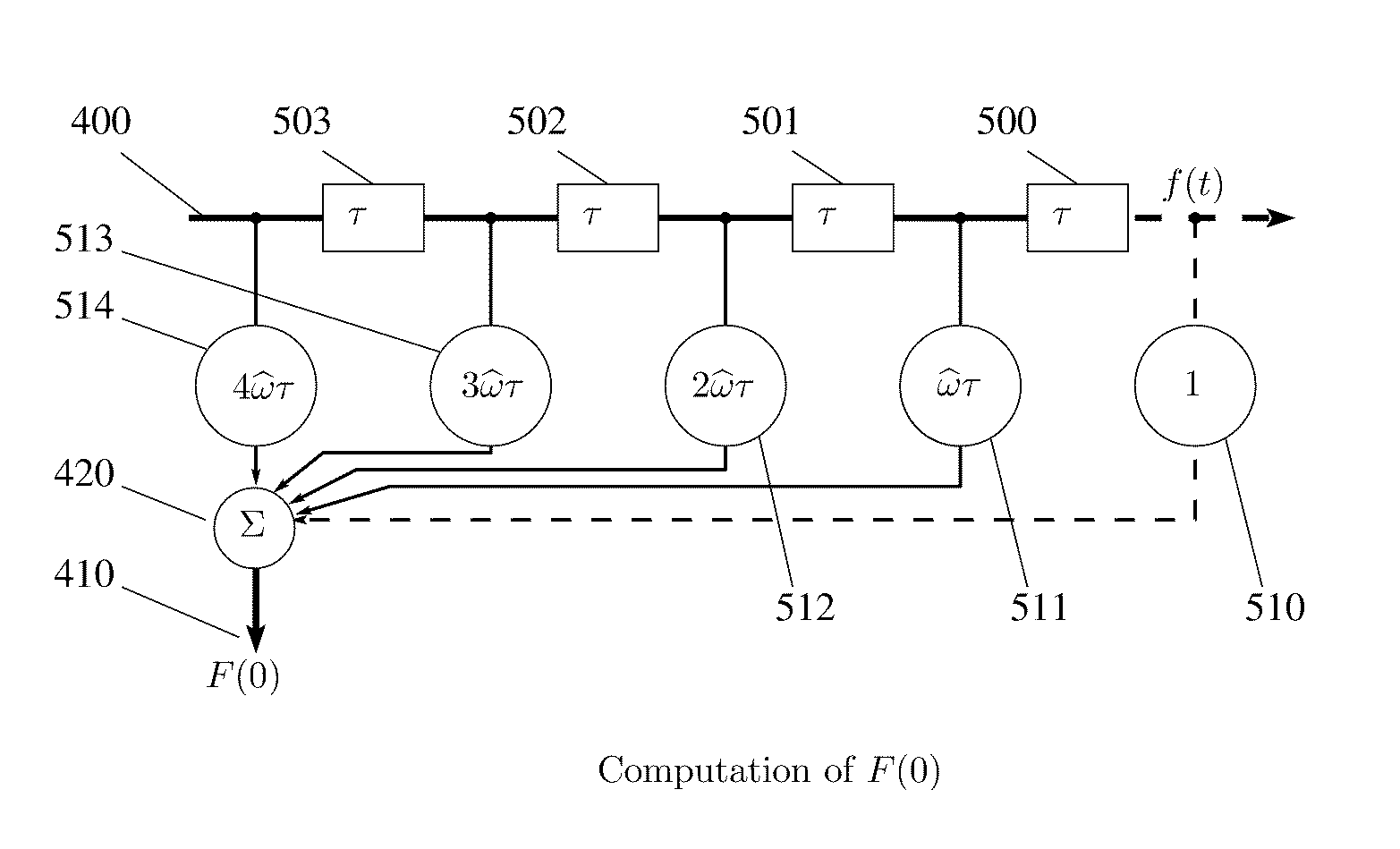
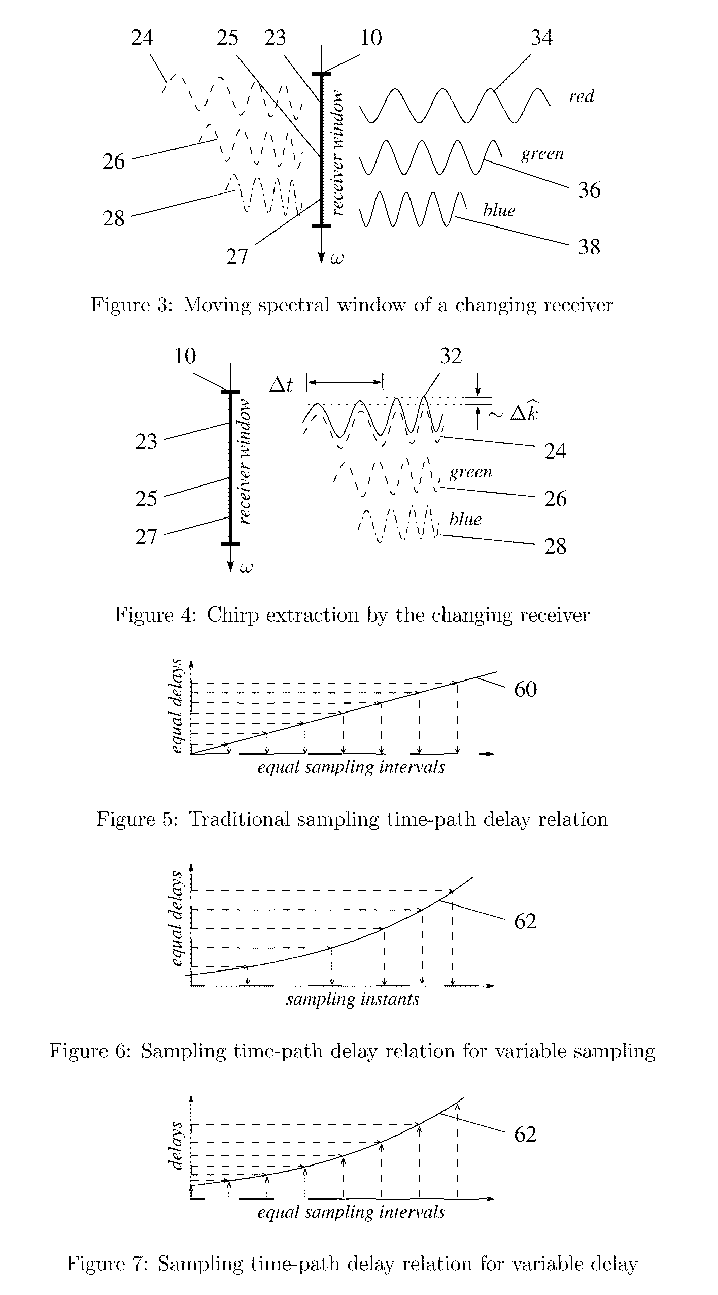
[0080]Accordingly, the principle of the present invention is to transfer the temporal variation, required in the spectral analysis or selection process of a receiver for obtaining distance-dependent scaling of received frequencies, from the individual grating or sampling intervals at the receiver front end or at the front end of the spectral analysis or selection process, where they would be difficult to incorporate, to a subsequent set of path delays generally having a bulk character and being also easier to vary in a controlled manner.

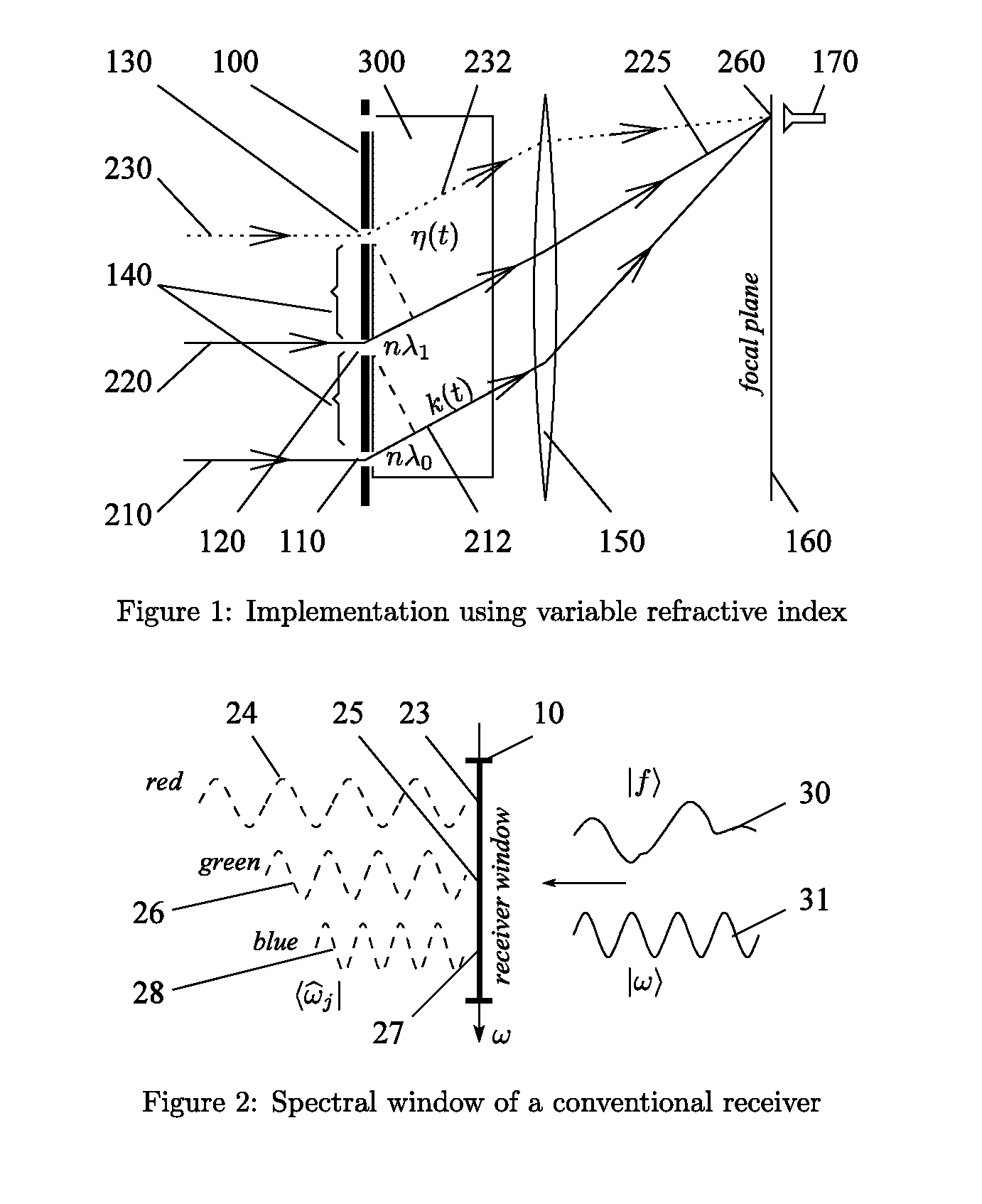
[0081]The preferred embodiment of the present invention accordingly comprises physical or computational means for effecting these path delays and for varying them both temporally, as required by the inventive principle, and spatially, as required for specific cases like correlation spectroscopy. The variable refractive index form of the preferred embodiment for optical implementations will be described first, to illustrate the principle.

[0082]The phy...


PUM


Abstract

In a receiver of electromagnetic or other waves, scaling of received frequencies in proportion to the respective source distances, so as to reveal the source distances and permit isolation of signals from a particular source by simple spectral filtering. Phase differences between transmitted frequencies due to the common source path lead to chirp eigenfunctions registering in the receiver as scaled frequencies. The chirps are extracted by implementing exponentially varying path delays in autocorrelators and diffractive spectrometers say using a medium with variable refractive index. Analogous exponentially varying phase shifts are applied to successive samples in the kernel of discrete Fourier transform implementations. Advantage lies in enabling distance-dependent frequency scaling in autocorrelation spectroscopy, as well as in conventional diffractive or refractive spectrometers or digital signal processing with uniform sampling.

Description

RELATED APPLICATIONS[0001]This application is a 371 of International Application No. PCT / US06 / 05103 filed Feb. 14, 2006, which claims benefit of U.S. Provisional Patent Application No. 60 / 698,459 filed Jul. 13, 2005.BACKGROUND OF THE INVENTION[0002]1. Technical Field[0003]This invention pertains to determination of the distance from a receiver of a source of electromagnetic or other waves, and to separation of signals from different sources depending on the respective distances. More particularly, it concerns extraction of spectral components so as to exhibit a dependence on the distances of the sources that can then be used for determining the source distance or for separating the signals from individual sources.[0004]2. Brief Description of the Prior ArtDistance-Dependent Scaling of Frequencies[0005]In a first copending application, titled “Passive distance measurement using spectral phase gradients”, filed 2 Jul. 2004, Ser. No. 10 / 884,353, and incorporated herein by reference, a ...

Claims


Application Information

Patent Timeline
Patent Type & Authority Patents(United States)
IPC IPC(8): G01S3/02G01S11/12G01S3/782G06F19/00H04L27/26G01S11/02
CPCH04L27/2647G01S11/12G01S3/782G01S3/02
Inventor GURUPRASAD, VENKATA
Owner GURUPRASAD VENKATA
Why Eureka
Try Eureka