Pulse radar device
a pulse radar and impulse-type technology, applied in the field of pulse radar devices, can solve the problems of high cost of devices that require all of the individual circuits to exhibit ultra-wideband characteristics, incompatible configuration with complicated circuit configuration, and distortion of pulse waveforms, etc., to achieve low cost, simple structure, and large signal-to-noise ratio
- Summary
- Abstract
- Description
- Claims
- Application Information
AI Technical Summary
Benefits of technology
Problems solved by technology
Method used
Image
Examples
first embodiment
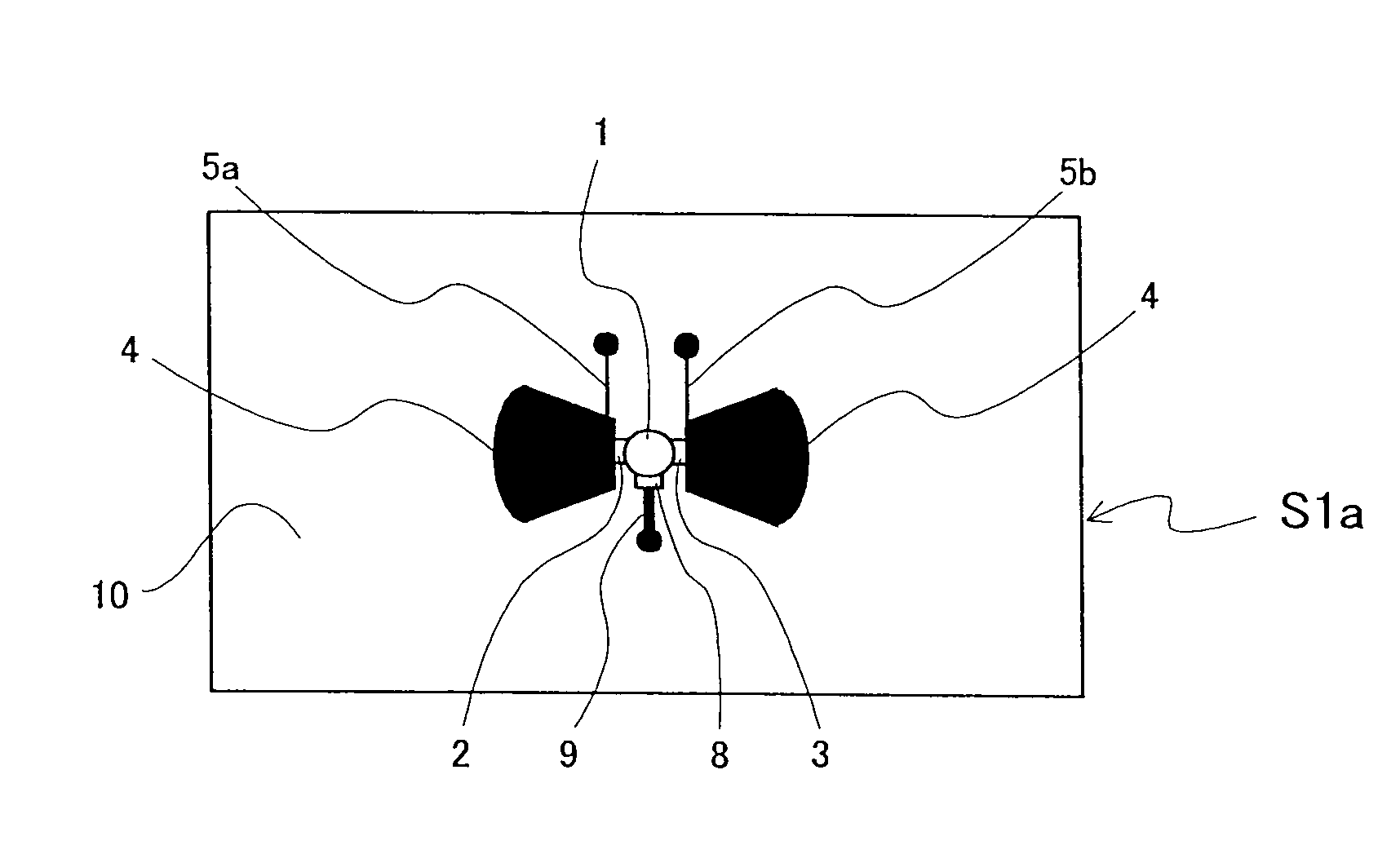
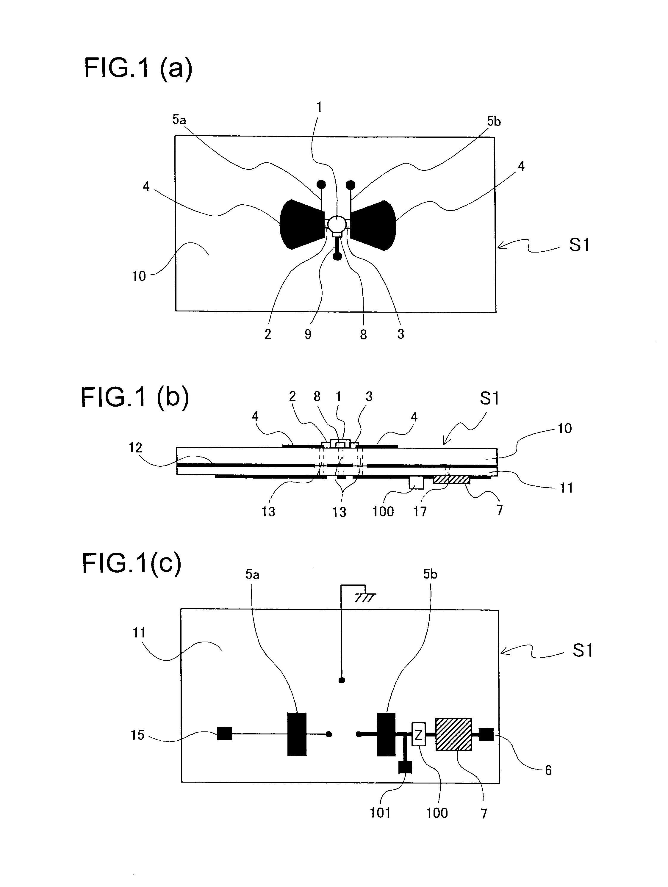
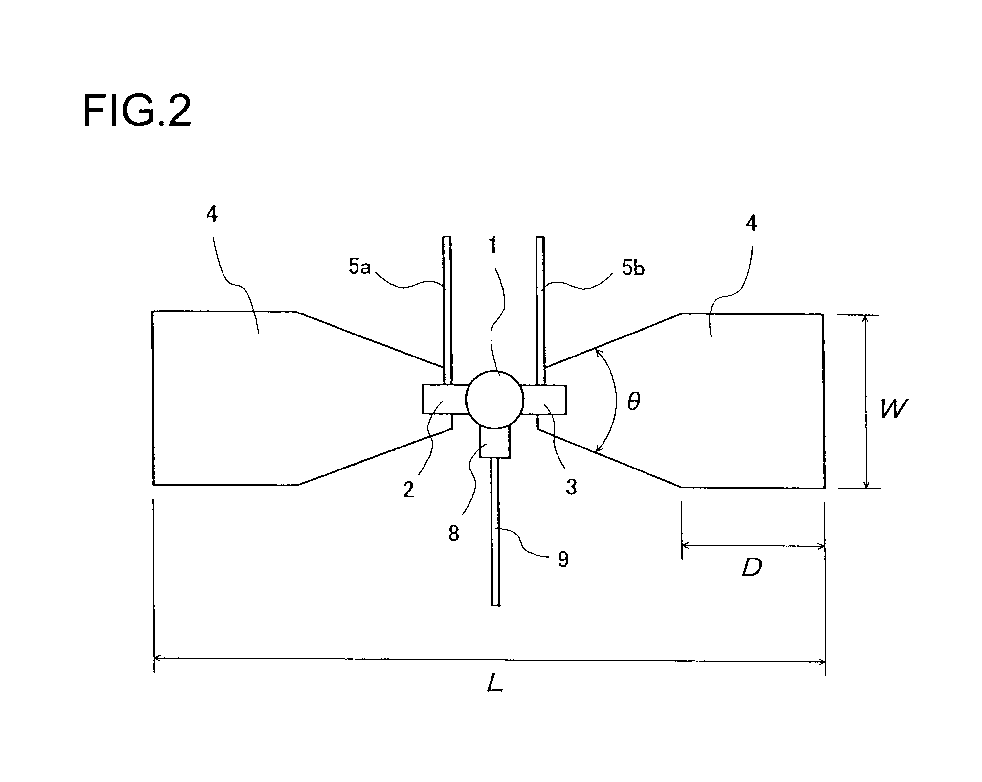
[0065]FIG. 1 shows the basic configuration of a pulse radar device according to a This pulse radar device comprises a radiation type oscillator substrate S1, a signal source that supplies a base band signal thereto (not shown), a power supply that performs DC bias feed (not shown), and a processor that performs analysis and processing of an acquired IF signal (not shown).
[0066]The radiation type oscillator substrate S1 here functions as a “radiation type oscillator that integrates a three-electrode high-frequency amplifying device to generate negative resistance in a resonant cavity and shares an antenna function for radiating an electromagnetic wave into space.” And the high-frequency pulse signal radiated into space by this radiation type oscillator is a transmitted RF signal, a reflected wave of the transmitted RF signal from an object of detection is a received RF signal, and when the received RF signal enters the radiation type oscillator, the radiation type oscillator is caus...
second embodiment
[0088]A pulse radar device will be explained next based on FIG. 6.
[0089]The pulse radar device of the present embodiment comprises a radiation type oscillator substrate S2, a signal source that supplies a base band signal thereto (not shown), a power supply that performs DC bias feed (not shown), and a processor that performs analysis and processing of an acquired IF signal (not shown). Further, the radiation type oscillator substrate S2 of the pulse radar device of the present embodiment configures the required circuits using a three-layer substrate with an inner-layer GND 12 constituting a grounding conductor layer sandwiched between a front-side dielectric substrate 10 and a rear-side dielectric substrate 11; an RF circuit section of the radiation type oscillator is constituted by the front surface and the inner-layer GND 12; and an RF choke circuit and a base band circuit are constituted by the inner-layer GND 12 and the rear surface. In addition, a monopulse generation circuit...
third embodiment
[0119]Next, the pulse radar device will be explained based on FIG. 20. The pulse radar device of the present embodiment is provided on a radiation type oscillator substrate S3 (whose high-frequency pulse generating and radiating structure is the same as the radiation type oscillator substrate S2, S1a, S1b, S1c, S2 or S2a set out in the foregoing and whose operation is also the same) with a Frequency Selective Surface (FSS) as a frequency selective filter means. Further, a grounding conductor structure is provided for preventing leakage of unnecessary signal components of a frequency lower than the frequency of the radiated high-frequency pulse signal (e.g., a base band signal component or monopulse signal component).
[0120]On the radiation direction side of the radiation type oscillator substrate S3 is arranged an FSS substrate 31 patterned on the side of the inner surface (surface facing the radiation surface of the radiation type oscillator substrate S3) with a low-pass filter pat...
PUM
 Abstract
Description
Claims
Application Information
 - R&D
- Intellectual Property
- Life Sciences
- Materials
- Tech Scout
- Unparalleled Data Quality
- Higher Quality Content
- 60% Fewer Hallucinations
Browse by: Latest US Patents, China's latest patents, Technical Efficacy Thesaurus, Application Domain, Technology Topic, Popular Technical Reports.
© 2025 PatSnap. All rights reserved.Legal|Privacy policy|Modern Slavery Act Transparency Statement|Sitemap|About US| Contact US: help@patsnap.com


