Method for producing a multilayer coating and device for carrying out said method

US8956511B2Active Publication Date: 2015-02-17LEYBOLD OPTICS

Image

  • Method for producing a multilayer coating and device for carrying out said method
  • Method for producing a multilayer coating and device for carrying out said method
  • Method for producing a multilayer coating and device for carrying out said method

Examples


Embodiment Construction

[0038]With the method of the invention, coatings with low optical losses can be made by reactive sputtering without breaking the vacuum, which contain reaction components such as oxygen, carbon or nitrogen. A production of oxides is described hereinafter; the method is, however, also suitable for carbides or nitrides or mixtures such as oxynitrides or carbonitrides or the like, while also 2 or more reactive gases can be used simultaneously as reactive components.

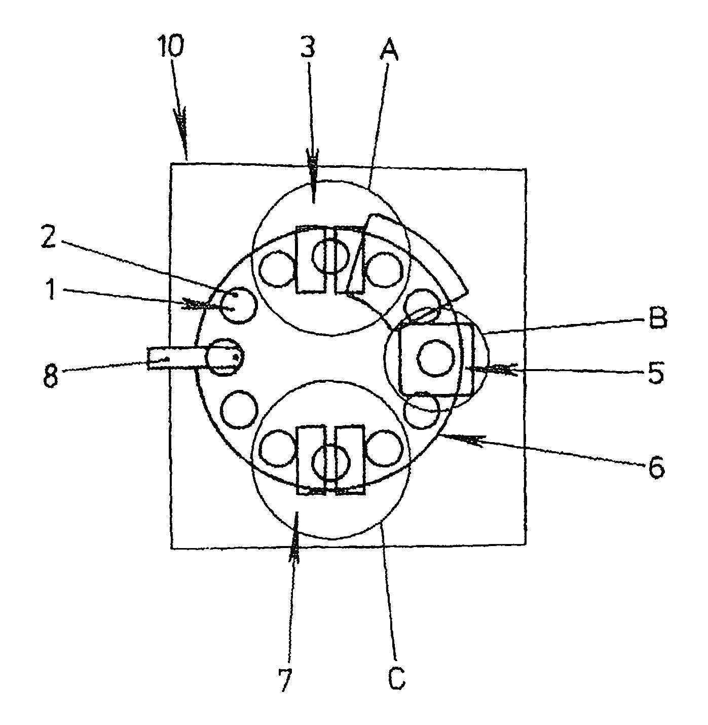
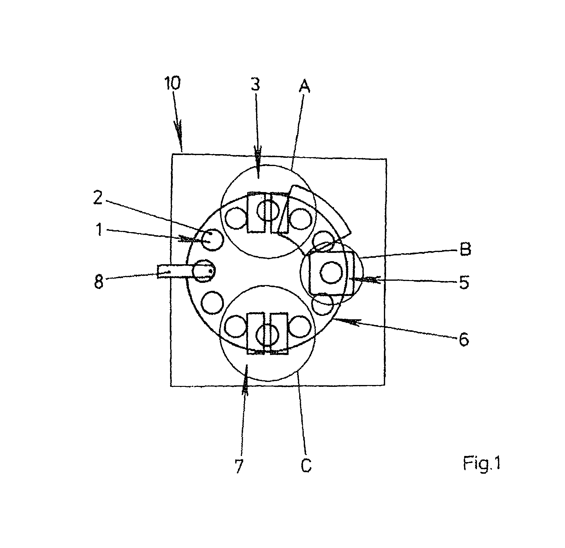
[0039]FIG. 1 shows a schematic drawing of a preferred system for depositing a coating according to one embodiment of the invention. An oxide coating is deposited with a residual gas on a substrate 2 in a vacuum chamber 10. The vacuum chamber 10 is divided into several areas, A, B and C. Preferably each area A, B and C has its own gas delivery, not shown, as well as its own pump supply. Also, more than three such areas can be provided. Areas A, B and C are preferably divided off from one another by diaphragms which are connec...


PUM

PropertyMeasurementUnit
Fractionaaaaaaaaaa
Fractionaaaaaaaaaa
Thicknessaaaaaaaaaa

Abstract

A method for reducing the optical loss of the multilayer coating below a predetermined value in a zone by producing coating on a displaceable substrate in a vacuum chamber with the aid of a residual gas using a sputtering device. Reactive depositing a coating on the substrate by adding a reactive component with a predetermined stoichiometric deficit in a zone of the sputtering device. Displacing the substrate with the deposited coating into the vicinity of a plasma source, which is located in the vacuum chamber at a predetermined distance from the sputtering device. The plasma action of the plasma source modifying the structure and / or stoichiometry of the coating, preferably by adding a predetermined quantity of the reactive component to reduce the optical loss of the coating.

Description

[0001]This application is a §371 from PCT / EP2003 / 013649 filed Dec. 3, 2003, which claims priority from DE 102 56 877.4 filed Dec. 4, 2002 and DE 103 47 521.4 filed Oct. 13, 2003, all of which are incorporated by reference in their entireties.BACKGROUND OF THE INVENTION[0002]The invention relates to a method for producing thin coatings and to an apparatus for the practice of the method.[0003]Many different methods are known in the field of physical and chemical depositing technologies for the production of thin coatings. Different methods are used according to the desired properties of the coating to be deposited and on the material systems chosen.[0004]The method of cathode sputtering is advantageous, especially for materials of high melting point, in which a plasma is ignited in a vacuum in a range that is clearly above any typical residual gas pressure for vapor depositing processes, by using an electrical field from which ions are accelerated against a target that is at a high el...

Claims


Application Information

Patent Timeline
17 Feb 2015
Publication
US8956511B2
IPC
C23C14/00; C23C14/32; C03C17/245; C23C14/02; C23C14/08; C23C14/34; C23C14/54; C23C14/58; H01J37/34
CPC
C23C14/0094; C23C14/0078; C23C14/024; C23C14/08; C23C14/547; H01J37/34; H01J2237/3321
Inventors
SCHERER, MICHAEL; PISTNER, JURGEN