
Treatment method and treatment facilities of exhaust gas

a technology of exhaust gas treatment and treatment facilities, which is applied in the direction of machines/engines, lighting and heating apparatus, and separation processes, etc., can solve the problems of complex handling, shortening the life of materials, and violent corrosion of the inside of the wet electrostatic precipitator

Active Publication Date: 2015-03-03
MITSUBISHI HITACHI POWER SYSTEMS ENVIRONMENTAL SOLUTIONS LTD
View PDF26 Cites 7 Cited by
  • Summary
  • Abstract
  • Description
  • Claims
  • Application Information

AI Technical Summary

Benefits of technology

The present patent is about using inorganic ammonium salt in a wet type flue gas desulfurization system. By using this neutral compound, the system is easier to handle compared to using ammonia gas from a compressed-gas cylinder. The inorganic ammonium salt can be fed from a liquid or solid state and can easily be mixed into an exhaust gas containing sulfur dioxide gas. This improves corrosion resistance of the plant and increases the longevity of the system. The pH value of the sulfuric acid mist after wet type desulfurization can also be measured to enhance the efficiency of the system.

Problems solved by technology

Thus, SO3 cannot be adequately removed by the wet type flue gas desulfurization equipment and therefore, a wet type electrostatic precipitator is separately provided subsequent to the wet type flue gas desulfurization equipment to remove SO3.
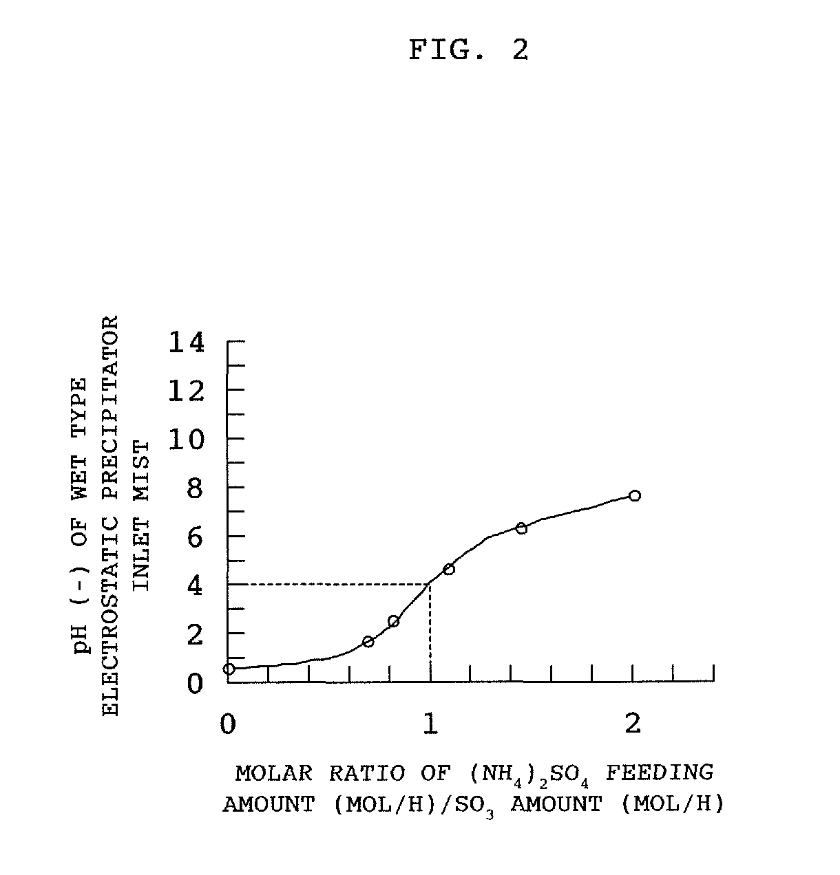
However, a mist introduced into the wet type electrostatic precipitator has SO3 as a main component and pH thereof is smaller than 2 and thus, the inside of the wet type electrostatic precipitator is subject to violent corrosion.
Also, a heat sinking unit of a gas-gas heater subsequent to the electrostatic precipitator has a problem of shortened life of material due to a sulfuric acid mist sticking to the surface of a pipe group and concentrated by an evaporation process.
As shown in Japanese Patent Application Laid-Open No. 2007-260619, equipment such as a compressed gas cylinder of ammonia and a pressure control valve is needed to feed an ammonia gas to allow a reaction with a sulfuric acid mist into the plant and such equipment has a problem of complicated handling.

Method used


Image

  • Treatment method and treatment facilities of exhaust gas
  • Treatment method and treatment facilities of exhaust gas
  • Treatment method and treatment facilities of exhaust gas

Examples


Embodiment Construction

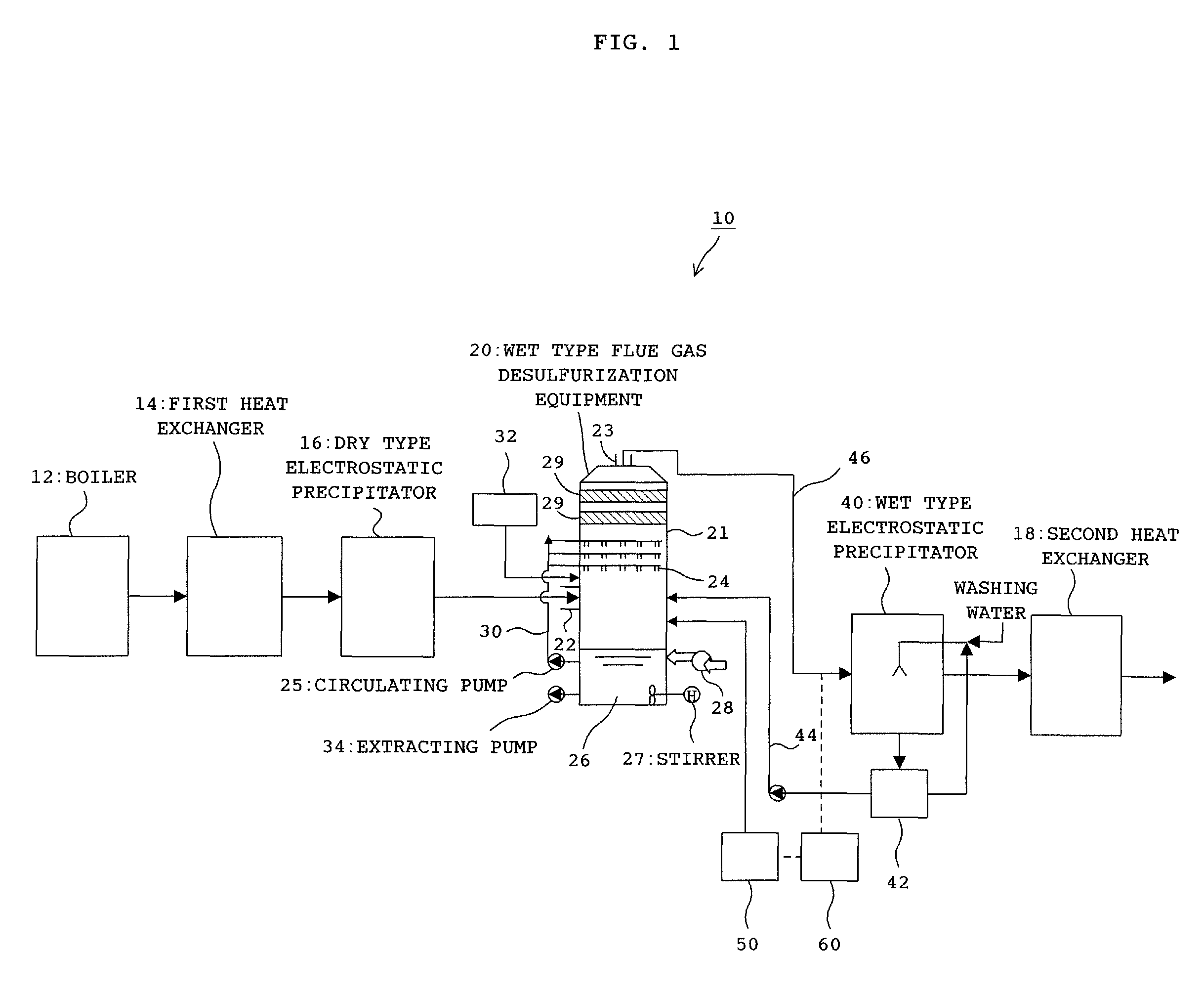
[0013]A treatment method and a plant of an exhaust gas according to the present invention will be described in detail below with reference to appended drawings.

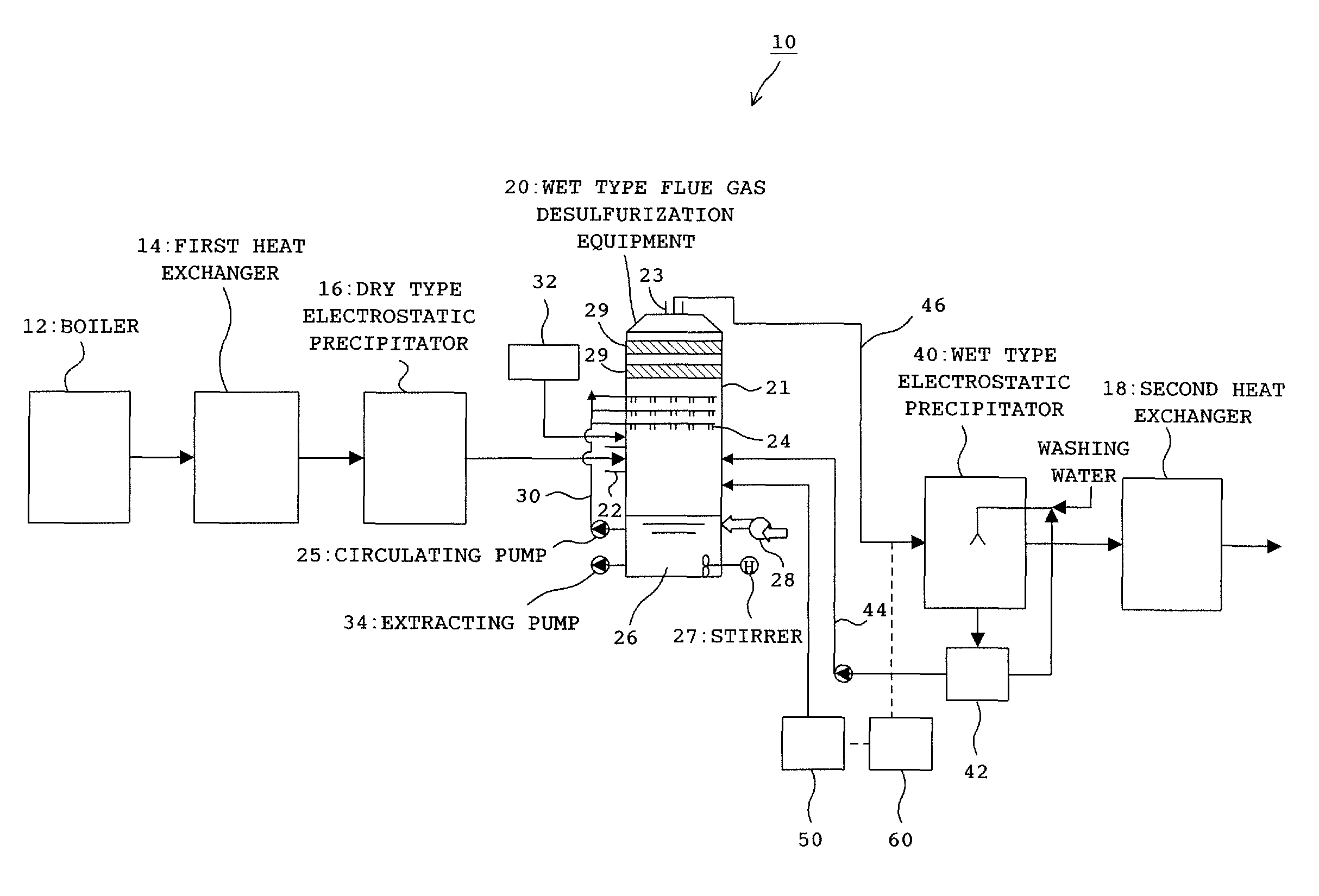
[0014]FIG. 1 is a diagram showing a schematic configuration of an exhaust gas treatment plant according to the present embodiment. As shown in FIG. 1, an exhaust gas treatment plant 10 according to the present invention includes a boiler 12, a first heat exchanger 14, a dry type electrostatic precipitator 16, wet type flue gas desulfurization equipment 20, a wet type electrostatic precipitator 40, and a second heat exchanger 18 as basic elements and elements from the boiler 12 to a chimney (not shown) are disposed in this order.

[0015]An exhaust gas discharged from the boiler 12 is introduced into the first heat exchanger 14. A gas-gas heater can be used as an example of the first heat exchanger 14. In the first heat exchanger 14, the air such as the air for combustion is preheated using heat of the exhaust gas. More specifica...


PUM

PropertyMeasurementUnit
pHaaaaaaaaaa
concentrationsaaaaaaaaaa
particle sizeaaaaaaaaaa

Abstract

An object of the present invention is to provide a treatment method and a plant of an exhaust gas in which corrosion resistance of the exhaust gas treatment plant to a sulfuric acid mist after wet type desulfurization is increased. The treatment method of an exhaust gas in the present invention, wherein sulfur oxide is removed by wet type desulfurization of the exhaust gas and a sulfuric acid mist is removed by feeding ammonia into the exhaust gas, is characterized in that an ammonia gas is mixed into the exhaust gas by feeding inorganic ammonium salt to an alkali desulfurizing agent when the desulfurizing agent is sprayed into the exhaust gas to absorb and remove the sulfur oxide in the exhaust gas.

Description

BACKGROUND[0001](a) Field of the Invention[0002]The present invention relates to an exhaust gas treatment method and treatment facilities that remove a sulfuric acid mist in an exhaust gas by a wet type electrostatic precipitator.[0003](b) Description of the Related Arts[0004]Exhaust gases given off from boilers, combustion furnaces and the like using petroleum, heavy oil and the like as fuel contain sulfur oxides such as sulfur dioxide and sulfur trioxide. Particularly, a heavy oil exhaust gas containing sulfur components in high concentrations has high content of SO3 in the exhaust gas.[0005]In a conventional exhaust gas treatment plant, a dry type electrostatic precipitator and a wet type flue gas desulfurization equipment are disposed in this order subsequent to a boiler. An exhaust gas discharged from the boiler is dusted by the dry type electrostatic precipitator before being introduced into the wet type flue gas desulfurization equipment. In the wet type flue gas desulfurizat...

Claims


Application Information

Patent Timeline
Patent Type & Authority Patents(United States)
IPC IPC(8): B01D53/52B01D53/50
CPCB01D53/502B01D2251/2062B01D2251/404
Inventor MOCHIZUKI, YOSHIHIKOOHASHI, NAOYUKI
Owner MITSUBISHI HITACHI POWER SYSTEMS ENVIRONMENTAL SOLUTIONS LTD
Learn More