Transparent contacts organic solar panel by spray

a solar panel and transparent technology, applied in the field of organic solar cells, can solve the problems posting difficulties in large-scale manufacturing, and achieve the effect of limiting the transparency of solar cells

Inactive Publication Date: 2015-03-17
UNIV OF SOUTH FLORIDA
View PDF18 Cites 0 Cited by
  • Summary
  • Abstract
  • Description
  • Claims
  • Application Information

AI Technical Summary

Benefits of technology

[0010]Conventional technology based on spin-coating and using metal as cathode contact greatly limits transparency of solar cells and posts difficulty for large scale manufacturing. The present invention provides a new spray technology that solves these two problems simultaneously using thin film organic layers applied via a layer-by-layer spray technique. The inverted organic solar photovoltaic cell may be fabricated onto most any desired substrates, both rigid and flexible. Exemplary substrates include cloth, glass, and plastic. For example, the substrate may be a low alkaline earth boro-aluminosilicate glass.
[0018]The resulting inverted organic solar photovoltaic cell uses all solution-processable organic solar layers with transparent contacts, allowing for improved transmittal of light trough the inverted organic solar photovoltaic cell. Current power conversion efficiency of −1.3% is achieved for a single cell with an active area of four millimeters squared (4 mm2), and provides an open circuit voltage of 0.39 volts and a short circuit current of 0.46 mA.

Problems solved by technology

Conventional technology based on spin-coating and using metal as cathode contact greatly limits transparency of solar cells and posts difficulty for large scale manufacturing.

Method used


Image

  • Transparent contacts organic solar panel by spray
  • Transparent contacts organic solar panel by spray
  • Transparent contacts organic solar panel by spray

Examples


example 1

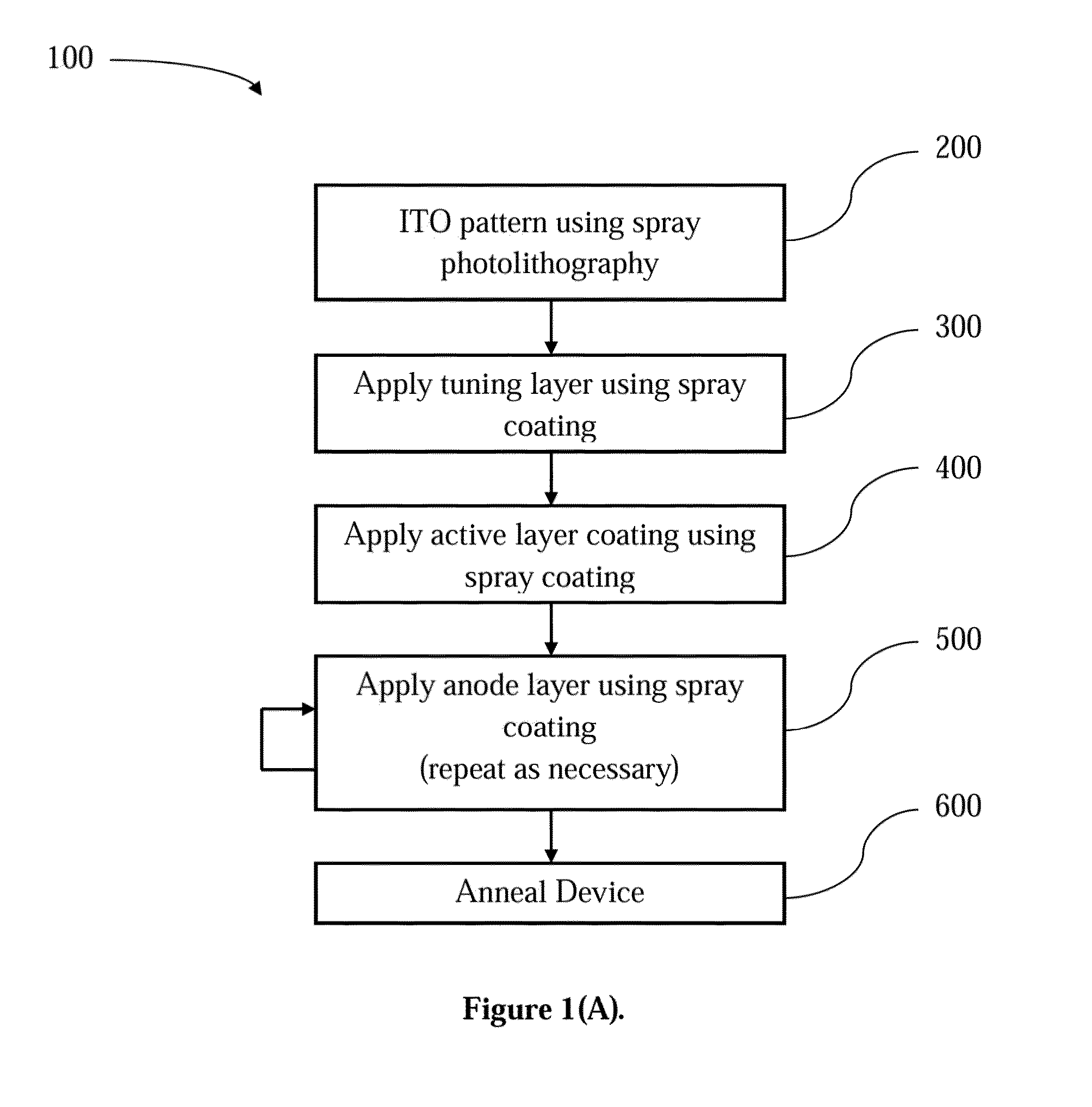
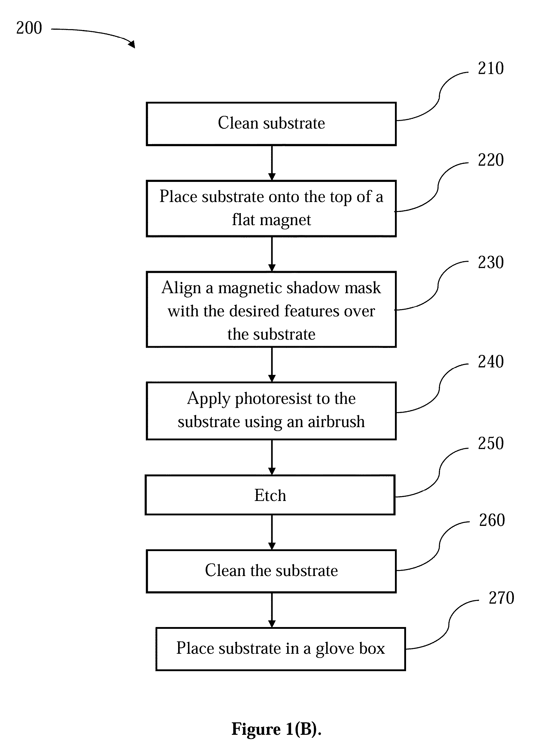
[0056]An indium tin oxide (ITO) with and Corning® low alkaline earth boro-aluminosilicate glass substratehaving a nominal sheet resistance of 4-10 Ω / square (Delta Technology, Inc. Phoenix, Ariz.) was pre-cut 4″×4″, and patterned using a positive photo resist, Shipley 1813, spray coated using an airbrush having a fine tip. The substrate was placed on top of a flat magnet and a magnetic shadow mask with desired features was aligned over the substrate. Shipley 1813 was spray coated using nitrogen (N2) as the carrier gas, set to 3 on a hotplate set to 130° C., depending on solution volume. The structure was removed from etchant and cleaned using sonication in trichloroethylene (TCE), followed by a sonication cleaning in acetone followed by isopropanol at 50° C. for 20 minutes for each cleaning. The structure was further cleaned using UV-ozone for thirty minutes. The patterned substrate was then placed in a glove box.

[0057]An interstitial layer was formed on top of the patterned ITO laye...

example 2

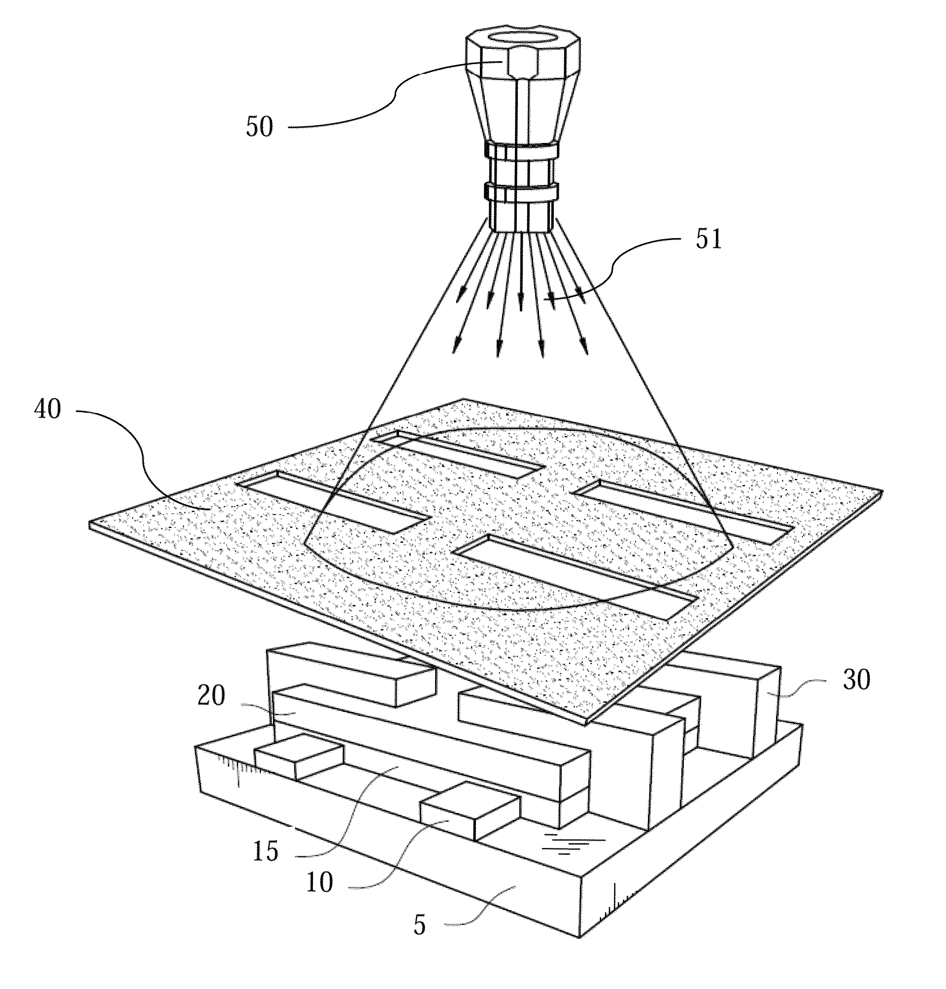
[0061]ITO glass substrates with a nominal sheet resistance of 4-10 Ω / square and Corning® low alkaline earth boro-aluminosilicate glass (Delta Technology, Inc., Tallahassee, Fla.), hereinafter substrate 5, were pre-cut 4″×4″ and cathode 10, also known as cathode layer, patterned as described in Example 1. As seen in FIG. 2(a), interstitial layer 15 was spray coated on top of patterned cathode layer 10 using a solution of 0.2% wt. Cs2CO3 (2 mg / mL; Sigma-Aldrich Co. LLC, St. Louis, Mo.) in 2-ethoxyethanol was prepared, as described above. Active layer 20 was prepared using a solution poly(3-hexylthiophene (Rieke Metals, Inc., Lincoln, Nebr.) and 6,6-phenyl C61 butyric acid methyl ester (Nano-C, Inc., Westwood, Mass.) at a weight ratio of 1:1 in dichlorobenzene and spray coated onto the Cs2CO3 coated substrate using an airbrush with N2 set to 30 psi, as described in Example 1.

[0062]Anode 30 was spray coated using aqueous, filtered solution of PEDOT:PSS mixed with 5 vol. % of dimethylsul...

example 3

[0066]Inverted organic photovoltaic cell 1 was created using the method described in Example 1, using substrate 5, a pre-cut 4″×4″ ITO glass substrates with a nominal sheet resistance of 4-10 Ω / square and Corning® low alkaline earth boro-aluminosilicate glass (Delta Technology, Inc., Tallahassee, Fla.). Cathode 10, comprised of ITO in the present example, was sprayed onto substrate 5 forming a ‘¦¦’ pattern extending from a first set of edges of substrate 5, as seen in FIG. 3. Interstitial layer 15 was sprayed onto cathode 10, except for the outermost edges, as seen in FIG. 4, and permits ITO to be used as a cathode, as discussed in Example 1. Active layer 20 was sprayed directly on top of interfacial buffer layer 15, seen in FIG. 5, and was prepared using poly(3-hexylthiophene) and 6,6-phenyl C61 butyric acid methyl ester. The active layer were chosen to provide a gradient for charges crossing the interface, approximating a conventional p-n junction with organic semiconductors, ther...


PUM

PropertyMeasurementUnit
thickaaaaaaaaaa
thickaaaaaaaaaa
thickaaaaaaaaaa

Abstract

A method of fabricating organic solar panels with transparent contacts. The method uses a layer-by-layer spray technique to create the anode layer. The method includes placing the substrate on a flat magnet, aligning a magnetic shadow mask over the substrate, applying photoresist to the substrate using spray photolithography, etching the substrate, cleaning the substrate, spin coating a tuning layer on substrate, spin coating an active layer of P3HT / PCBM on the substrate, spray coating the substrate with a modified PEDOT solution, and annealing the substrate.

Description

CROSS REFERENCE TO RELATED APPLICATIONS[0001]This application is a continuation-in-part of U.S. application Ser. No. 13 / 400,352, entitled “Transparent Contacts Organic Solar Panel by Spray”, filed Feb. 20, 2012, which is a continuation of International Application Serial Number PCT / US2010 / 058732 filed Dec. 2, 2010, which claims priority to U.S. Provisional Patent Application No. 61 / 265,963, filed Dec. 2, 2009, which is herein incorporated by reference.FIELD OF INVENTION[0002]This invention relates to organic solar cells; in particular, to a method of fabricating a thin film organic solar module using a novel layer-by-layer spray technique.BACKGROUND[0003]Organic solar cells (OSC) or organic photovoltaics (OPV) based on π-conjugated polymers (e.g. poly-3-hexylthiophene (P3HT)) and fullerene derivatives (e.g. [6,6]-phenyl C61 butyric acid methyl ester (PCBM)) have attracted attention over the past decades because they may provide a cost-effective route to wide use of solar energy for ...

Claims


Application Information

Patent Timeline
Patent Type & Authority Patents(United States)
IPC IPC(8): H01L21/00H01L51/40H01L31/00B05D5/12B82Y10/00B82Y20/00H01L51/00H01L51/42H01L51/44
CPCH01L51/0003B82Y10/00H01L51/0023B82Y20/00H01L51/442Y02E10/549H01L51/0036H01L51/0047H01L51/4253H10K71/12H10K71/621H10K85/215H10K85/113H10K30/82H10K30/30
Inventor LEWIS, JASONZHANG, JIANJIANG, XIAOMEI
Owner UNIV OF SOUTH FLORIDA
Why Eureka
Try Eureka