Eureka AIR delivers breakthrough ideas for toughest innovation challenges, trusted by R&D personnel around the world.

Method of manufacturing inverted organic solar microarray for applications in microelectromechanical systems

a microarray and microarray technology, applied in the field of spray-manufactured organic solar photovoltaic cells, can solve the problems of limiting the use of photovoltaic cells, complicated photovoltaic cell production processes, and strained natural resources, and achieves high temperature, low rate, and high-cost manufacturing.

Active Publication Date: 2016-08-23
UNIV OF SOUTH FLORIDA
View PDF5 Cites 0 Cited by
  • Summary
  • Abstract
  • Description
  • Claims
  • Application Information

AI Technical Summary

Benefits of technology

This patent describes a new spray technique for making photovoltaic cells and arrays using a thin film organic solar module. This technique solves problems of conventional technology such as limited transparency and difficulty in large-scale manufacturing. The method can be used on any type of substrate including cloth and plastic. The use of a self-assembled monolayer (SAM) improves device efficiency and reproducibility. The semi-transparent property of the solar module allows for applications on windows and windshields, and can be integrated into soft fabric substances such as tents, military back-packs or combat uniforms, providing a highly portable renewable power supply for deployed military forces. This technology can be used for large-scale, low-cost manufacturing of commercial photovoltaic products based on solutions of organic semiconductors.

Problems solved by technology

The increased energy consumption has strained natural resources, such as fossil fuels, as well as global capacity to handle the byproducts of consuming these resources.
However, these inorganic silicon-based photovoltaic cells are produced in complicated processes and at high costs, limiting the use of photovoltaic cells.
These silicon wafer-based cells are brittle, opaque substances that limit their use.
Both the ITO and aluminum contacts use sputtering and thermal vapor deposition, both of which are expensive, high vacuum, technologies.
However, this limits the materials that may be selected for the substrate and electrode.
Moreover, the organic photoelectric conversion layer is sensitive to oxygen and moisture, which reduce the power conversion efficiency and the life cycle of the organic solar cell.
However, stacking photoactive layers can cause layers to melt due to solvent formation from the different layers.
Stacking also limits the transparency of the photovoltaic.
However, the metal layer also reduces light transmittance, affecting power conversion efficiency of the photovoltaic cell.
However, in order for solar cells to be compatible with windows, issues with the transparency of the photovoltaic must first be addressed.
The metal contacts used in traditional solar modules are visibility-blocking and has to be replaced.
Another challenge is to reduce cost for large scale manufacturing in order for organic solar cells to be commercially viable, a much lower manufacturing cost to compensate for the lower efficiency than current photovoltaic products.
Large-scale manufacturing techniques, such as printing, have lowered the cost of manufacture, but still involve the use of metal in certain way, and therefore affect the transparency of the photovoltaic cell.

Method used


Image

  • Method of manufacturing inverted organic solar microarray for applications in microelectromechanical systems
  • Method of manufacturing inverted organic solar microarray for applications in microelectromechanical systems
  • Method of manufacturing inverted organic solar microarray for applications in microelectromechanical systems

Examples


example

[0034]The indium tin oxide (ITO) is patterned onto a glass substrate using a positive photo resist, such as Shipley 1813, spin coated at 4500 rpm and soft baked on a hotplate for 3 minutes at 90° C. The substrate is then exposed to a UV-lamp for 1.4 seconds in a constant intensity mode set to 25 watts. The structure was developed for about 2.5 minutes using Shipley MF319 and rinsed with water. The substrate was then hard-baked, at 145° C. for 4 minutes and any excess photoresist cleaned off with acetone and cotton. After cleaning, the substrate was etched from about 5-11 minutes with a solution of 20% HCl-7% HNO3 on a hotplate at 100° C. The etched substrate was then cleaned by hand using acetone followed by isopropanol and UV-ozone cleaned for at least 15 minutes.

[0035]The Self-Assembled Monolayer (SAM) layer was formed on top of the patterned ITO layer. A solution of N-propyl trimethoxysilane (3 mM) in ethanol was prepared and stirred for 10 minutes at room temperature. Once the S...

example 2

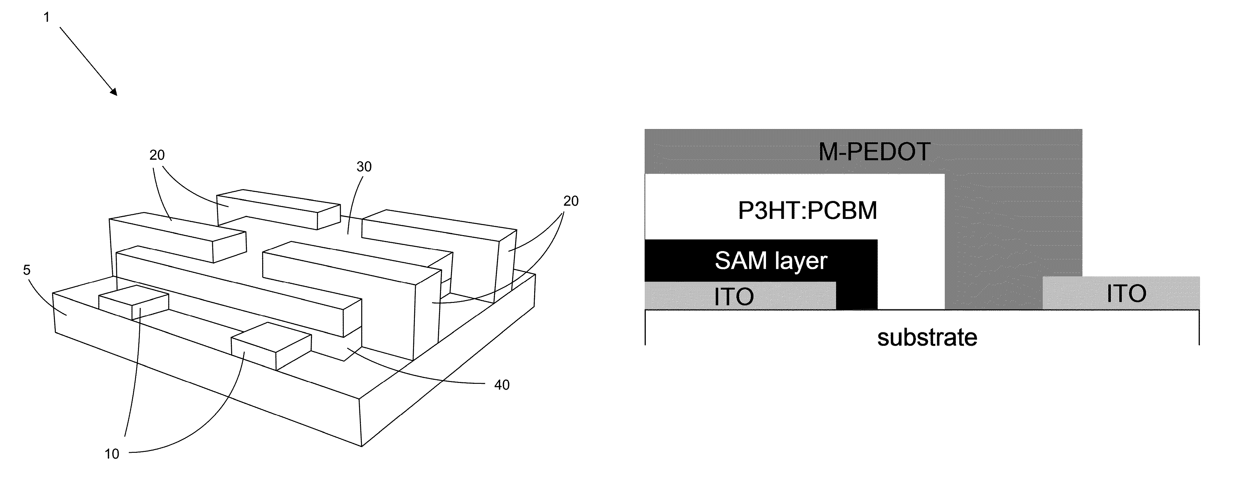
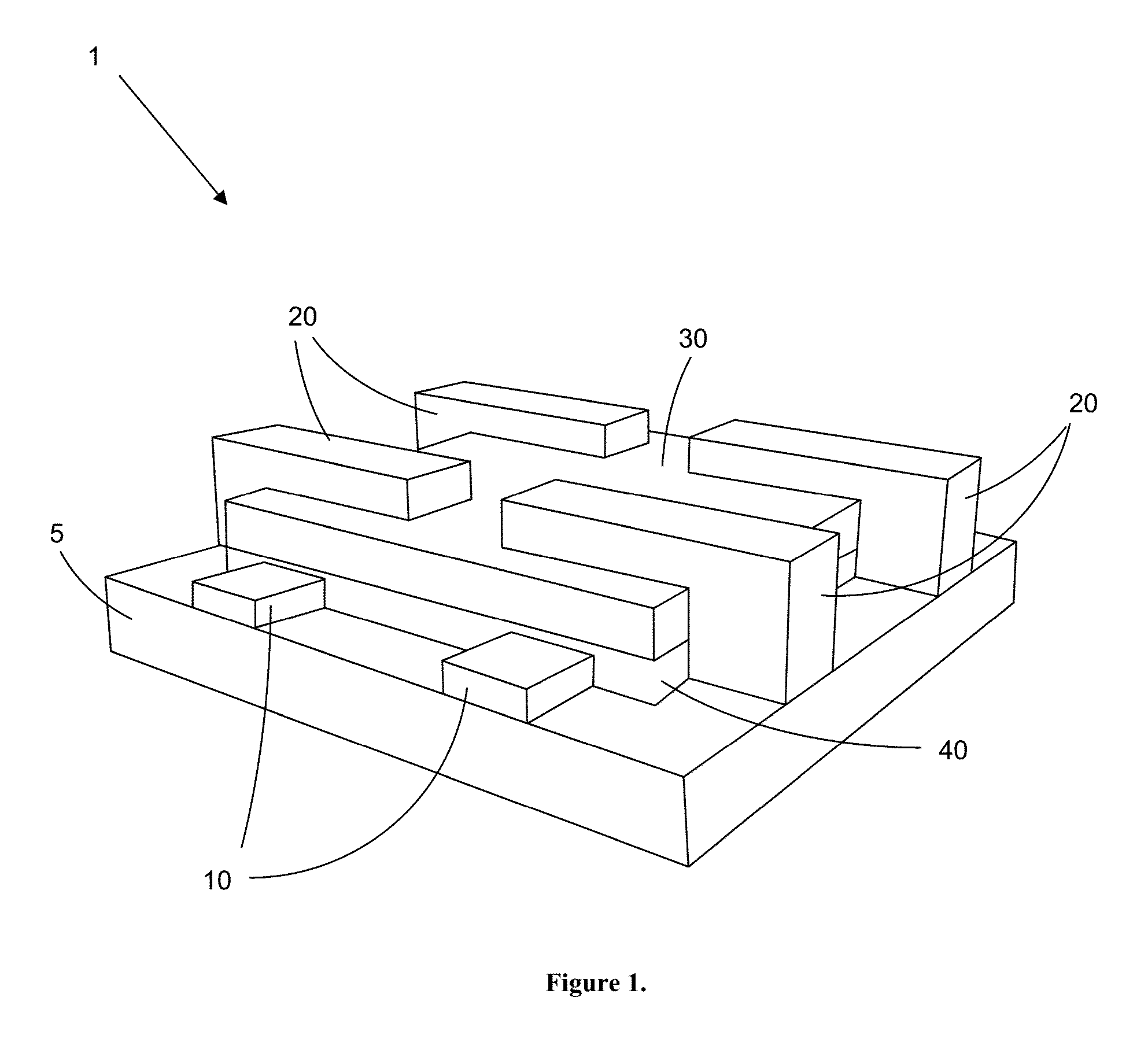
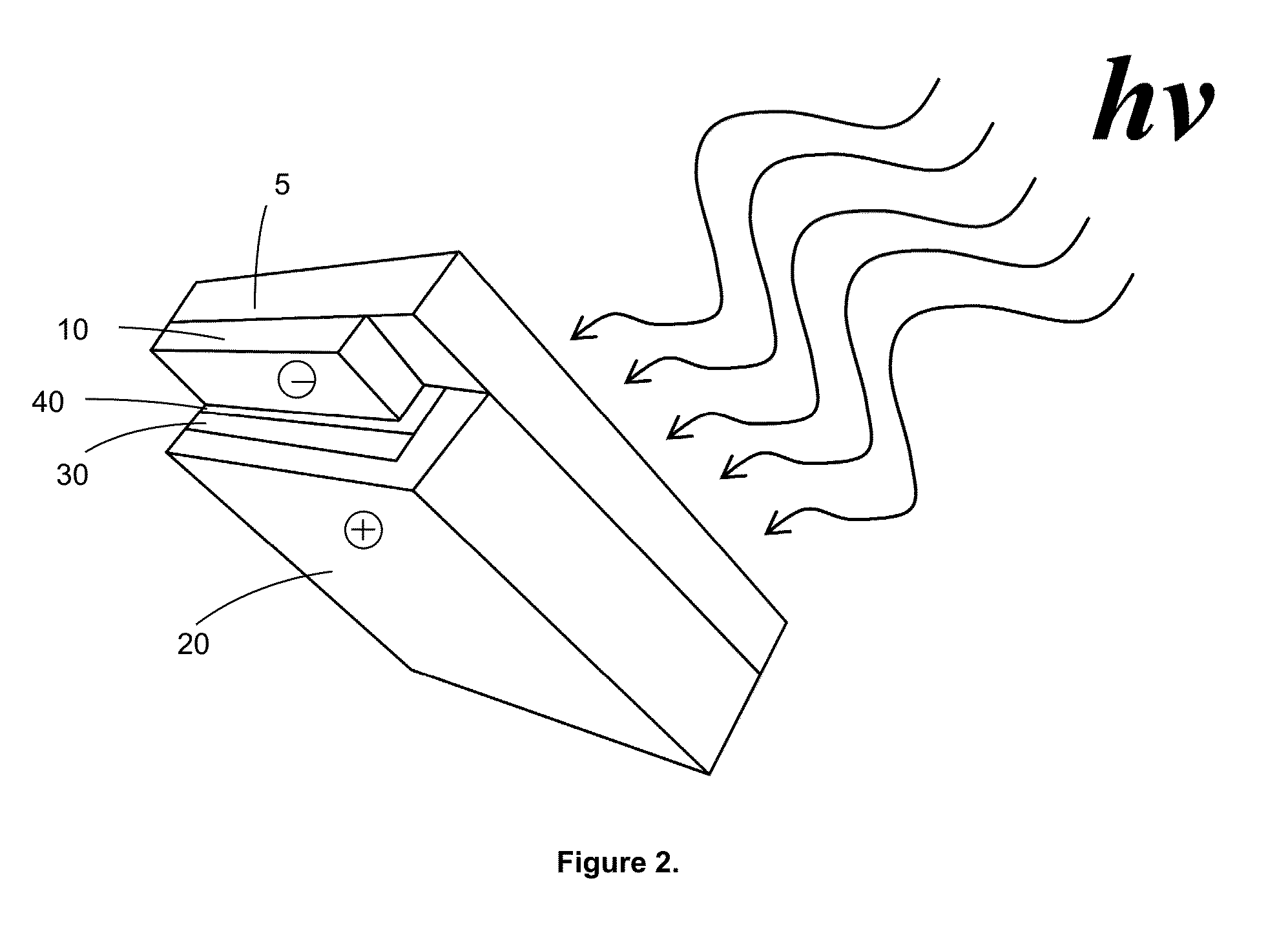
[0041]Inverted organic photovoltaic cell 1, seen dissected in FIG. 1, was created using the method described in Example 1. Inverted photovoltaic cell 1 was composed of different layers of active materials and terminals (anode and cathode) built onto substrate 5. Anode 10, comprised of ITO in the present example, was sprayed onto substrate 5 forming a ‘’ pattern extending from a first set of edges of substrate 5. SAM layer 40 covers anode 10, except for the outermost edges, as seen in FIG. 2. The components of the SAM layer were chosen to provide a gradient for charges crossing the interface, approximating a conventional p-n junction with organic semiconductors, thereby providing an increased efficiency of heterojunctions. Active layer 30 is disposed directly on top of interfacial buffer layer 40, and was prepared using poly(3-hexylthiophene) and 6,6-phenyl C61 butyric acid methyl ester. Anode 20 was disposed on the active layer in a pattern, similar to the cathode, but perpendicular...

example 3

[0043]Solar illumination has been demonstrated to improve solar array efficiency up to 250%. Device efficiency of 1.80% was observed with the array under AM1.5 irradiance. Data have shown that the performance enhancement under illumination only happens with sprayed devices, not devices made by spin coating (See, Lewis, et al., PCT / US11 / 54290). This means that solar cells made using the present spray-on technique perform better under sunlight, which is beneficial for solar energy application.

[0044]A solar array was prepared by forming 50 individual inverted cells as described above, each with an active area of 3000 mm2. The array was configured with 10 cells in series in one row to increase the voltage, and five rows in parallel connection to increase the current. The neighboring cells were connected using the organic layer configuration, seen in cross section in FIG. 4 and top view in FIG. 5.

[0045]The photovoltaic cells were then prepared in a 1″ by 1″ array comprises 60-1 mm2 cells...


PUM


Abstract

The fabrication and characterization of large scale inverted organic solar array fabricated using all-spray process is disclosed. Solar illumination has been demonstrated to improve transparent solar photovoltaic devices. The technology using SAM has potential to revolute current silicon-based photovoltaic technology by providing a complete solution processable manufacturing process. The semi-transparent property of the solar module allows for applications on windows and windshields. The inventive arrays are more efficient than silicon solar cells in artificial light environments, permitting use of the arrays in powering microelectromechanical systems and in integration with microelectromechanical systems.

Description

CROSS REFERENCE TO RELATED APPLICATIONS[0001]This application is a divisional application of U.S. application Ser. No. 14 / 021,620, entitled “Inverted Organic Solar Microarray for Applications in Microelectromechanical Systems”, filed on Sep. 9, 2013, which is a continuation of prior filed International Application, Serial Number PCT / US2012 / 028255 filed Mar. 8, 2012, which claims priority to U.S. Provisional Patent Application 61 / 450,425, entitled, “Inverted Organic Solar Microarray for Applications in Microelectromechanical Systems and Others”, filed 8 Mar., 2011, the contents of which are herein incorporated by reference.FIELD OF INVENTION[0002]This invention relates to spray-manufactured organic solar photovoltaic cell. Specifically, the invention provides a novel method of manufacturing organic solar photovoltaic cells using spray-deposition and the organic solar photovoltaic cell resulting therefrom.BACKGROUND OF THE INVENTION[0003]In recent years, energy consumption has drastic...

Claims


Application Information

Patent Timeline
Patent Type & Authority Patents(United States)
IPC IPC(8): H01L51/00H01L27/30H01L51/44H01L31/0256H01L31/048H01L51/42
CPCH01L27/301H01L51/442H01L31/0256H01L31/048H01L51/0003H01L51/0023H01L51/0036H01L51/0037H01L51/4253H01L2251/308Y02E10/549H01L51/0047Y02P70/521Y02P70/50H10K85/1135H10K85/215H10K85/113H10K30/82H10K30/30H10K2102/103H10K39/12H10K71/12H10K39/10H10K71/621
Inventor LEWIS, JASON ERIKJIANG, XIAOMEI
Owner UNIV OF SOUTH FLORIDA
Why Eureka
Eureka Blog
Learn More