Gas detection system using fiber laser with active feedback compensation by reference cavity

a fiber laser and reference cavity technology, applied in the field of fiber lasers, can solve the problems of reducing the detection accuracy of gas detection methods, and limiting the measurement sensitivity, so as to achieve high sensitivity, high precision, and high sensitivity

Inactive Publication Date: 2015-04-14
LUO FEI
View PDF4 Cites 8 Cited by
  • Summary
  • Abstract
  • Description
  • Claims
  • Application Information

AI Technical Summary

Benefits of technology

[0018]The gas detection system according to the present invention can take advantages of the unique superiority of the compact structure and narrow linewidth of the laser output of the fiber laser, and achieve a gas detection method with high sensitive and high precision by feedback controlling. The method and system are not limited to apply to high sensitivity detection of gas content, but also easily apply to the detection with high sensitivity and material analysis of other materials.

Problems solved by technology

However, generally the light source has a wide spectral linewidth, and some of the gases have very narrow absorption lines, so the optical power does not change obviously when passing through the gas chamber, which lowers and limits measuring sensitivity.
Especially, it is more difficult for detecting tiny gas concentration.
However, this detection method does not eliminate the detection error caused by the instability of the wavelength of light λ1, which can not be ignored in the practical detection.
However such a regulation method is passive, do not strictly eliminate fluctuations of the laser λ1, thus such an improvement do not obtain good effects.

Method used


Image

  • Gas detection system using fiber laser with active feedback compensation by reference cavity
  • Gas detection system using fiber laser with active feedback compensation by reference cavity
  • Gas detection system using fiber laser with active feedback compensation by reference cavity

Examples


Embodiment Construction

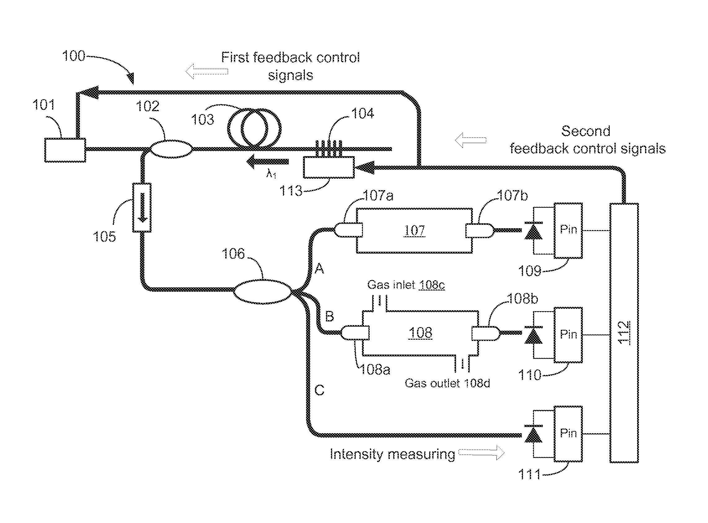
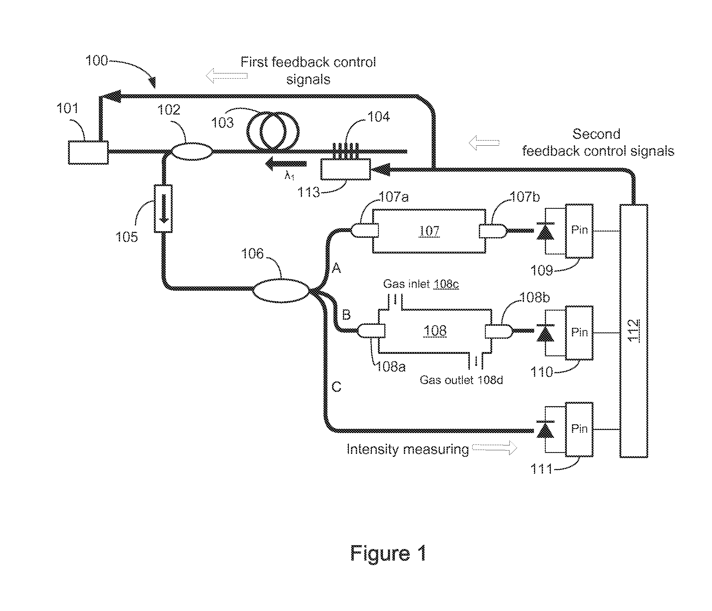
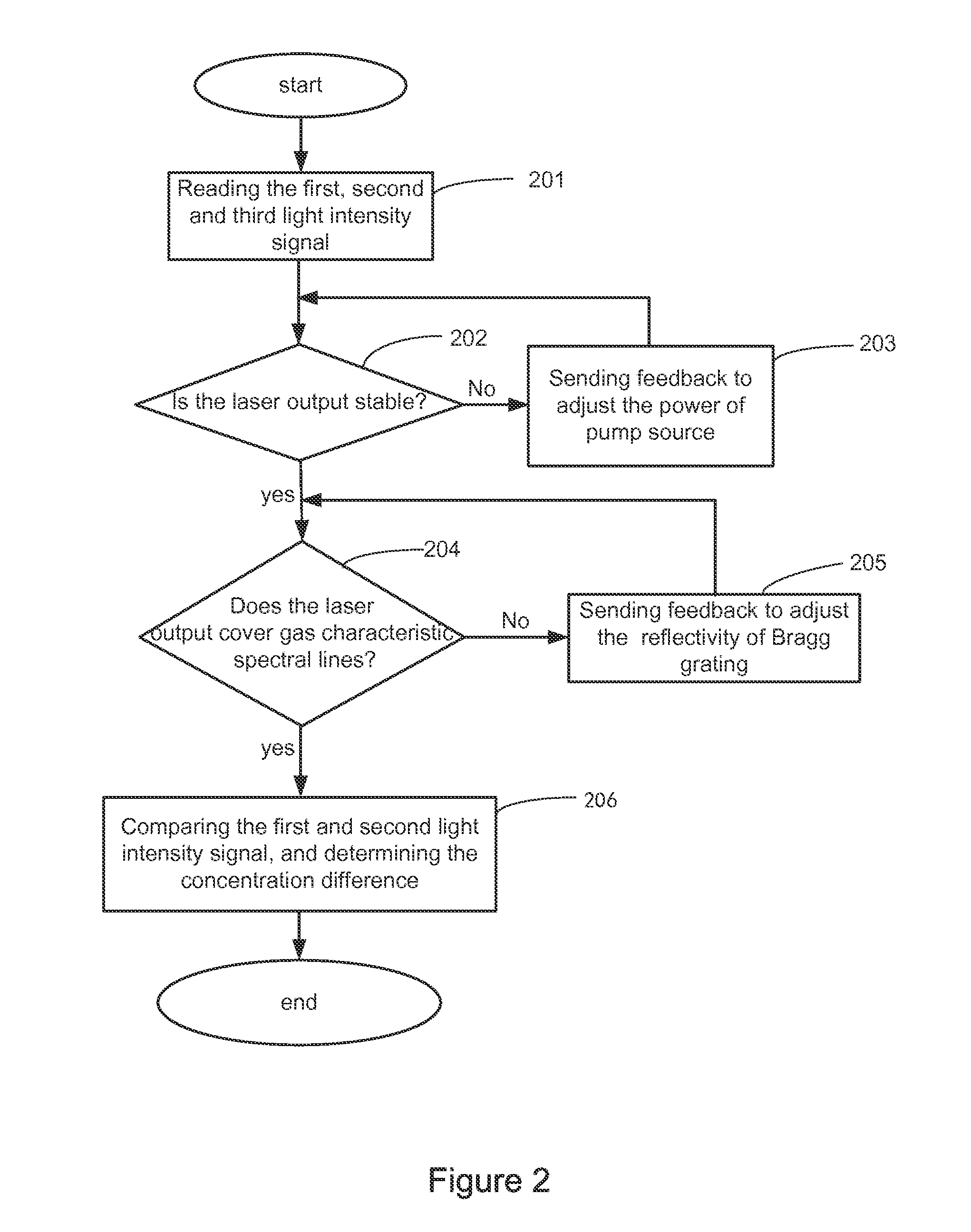
[0024]Hereinafter, embodiments of the present invention will be explained in details with reference to drawings. In the accompanying drawings, like reference numerals designate the same or similar parts, or the same or similar procedures.

[0025]With reference to the exemplary embodiments, the purpose and function of the present invention and method to achieve these purpose and function will be explained. However, the present invention is not limited to the disclosed exemplary embodiments, and can be implemented with different forms. The description in nature is merely to help those skilled in the art to comprehensively understand the specific details of the invention.

[0026]The present invention will be described in detail with reference to the schematic figures. For the purpose of explanation, when describing the invention in details, the sectional figures representing the device structure will be partial enlarged not in general proportion, and the schematic figures are only exemplar...


PUM

PropertyMeasurementUnit
reflectanceaaaaaaaaaa
core diameteraaaaaaaaaa

Abstract

The present invention provides a fiber laser gas detection system using active feedback compensation by a reference cavity, said system comprising: an optical fiber laser consists of a laser diode pump source, a wavelength division multiplexer, an active optical fiber and a fiber Bragg grating connected successively; an optical isolator coupled with said wavelength division multiplexer for blocking a reverse light transmission in said active fiber; a coupler connected with said optical isolator for dividing the laser light after being isolated by the optical isolator into a reference beam, a detecting beam and an intensity measuring beam according a certain ration power. The gas detection system according to the present invention can take advantages of the unique superiority of compact structure and narrow linewidth of the laser output of the fiber laser, and achieve a gas detection method with high sensitive and high precision by feedback controlling.

Description

CROSS-REFERENCE TO RELATED APPLICATIONS[0001]This non-provisional application claims priority under 35 U.S.C. §119(a) on Patent Application No. 2013104788372 filed in P.R. China on Oct. 14, 2013, the entire contents of which are hereby incorporated by reference.TECHNICAL FIELD[0002]The present invention relates to fiber laser, particularly relates to a gas detection system and method for the gas concentration measurement implemented by the distributed feedback fiber laser, which uses a reference cavity for active feedback compensation.BACKGROUND OF THE INVENTION[0003]Laser plays an important role in modern spectroscopy, due to its high monochromaticity (narrow spectral line), high brightness, high directivity and other unique advantages. A new laser spectroscopy develops, with a high application value in various research fields such as modern agriculture and environmental science, biology and medical science, physics, chemistry and materials science and astrophysics, and in industri...

Claims


Application Information

Patent Timeline
Patent Type & Authority Patents(United States)
IPC IPC(8): G01N21/00G01N21/61
CPCG01N21/61G01N2201/06113G01N2201/0635G01N21/3504G01N21/359
Inventor LUO, FEIZHU, LIANQINGDONG, MINGLIHE, WEIZHANG, YINMIN
Owner LUO FEI
Why Eureka
Try Eureka