
Ultrafast laser apparatus

a laser and ultra-fast technology, applied in the field of lasers, can solve the problems of weak nonlinear effects and pulse breakup, commercial amplified fiber laser sources now reach tens and even hundreds of micro-joules per pulse, and the power of such sources is limited, so as to improve the laser pulse energy, reduce the number of repetitions, and reduce the cost

Active Publication Date: 2015-06-02
BOARD OF TRUSTEES OPERATING MICHIGAN STATE UNIV
View PDF63 Cites 9 Cited by
  • Summary
  • Abstract
  • Description
  • Claims
  • Application Information

AI Technical Summary

Benefits of technology

The present patent describes a new laser apparatus that can generate very high power pulses of laser light. This apparatus is different from traditional methods because it uses a special waveform called a "chirped pulse amplification" to avoid strong nonlinear effects and pulse breakup. By using a flexible gain and passive fiber, the apparatus can be made compact and portable, while still providing high energy pulses. This new laser apparatus can be used for various applications, such as material processing, ablation, and spectroscopy. It is also suitable for laser-induced breakdown spectroscopy and endoscopy. Overall, the laser apparatus has the capability to generate high-power pulses with low repetition rates and is more efficient and cost-effective than traditional multi-stage amplified systems.

Problems solved by technology

The guidelines being outlined in the publication of A. Galvanauskas and M. Fermann, “Hybrid Diode-Laser Fiber-Amplifier Source of High-Energy Ultrashort Pulses,”Optics Letters, Vol. 19, No. 14, 1043 (1994), state that high peak intensities inevitably lead to strong nonlinear effects and pulse breakup.
While staying within these guidelines, which require complexity in the form of multiple amplification stages, commercial amplified fiber laser sources now reach tens and even hundreds of micro-Joules per pulse.
The first page of this publication states that “the power of such sources is limited” and “a pulsed erbium-doped fiber laser .
The goal of Horowitz is to produce a short coherence length light source and not an efficient laser source.
Furthermore, Horowitz comments in the last column: “Our laser cannot support short pulses because of the strong positive dispersion and the significant birefringence, which introduces significant PDD” (polarization-dependent delay).

Method used


Image

  • Ultrafast laser apparatus
  • Ultrafast laser apparatus
  • Ultrafast laser apparatus

Examples


Embodiment Construction

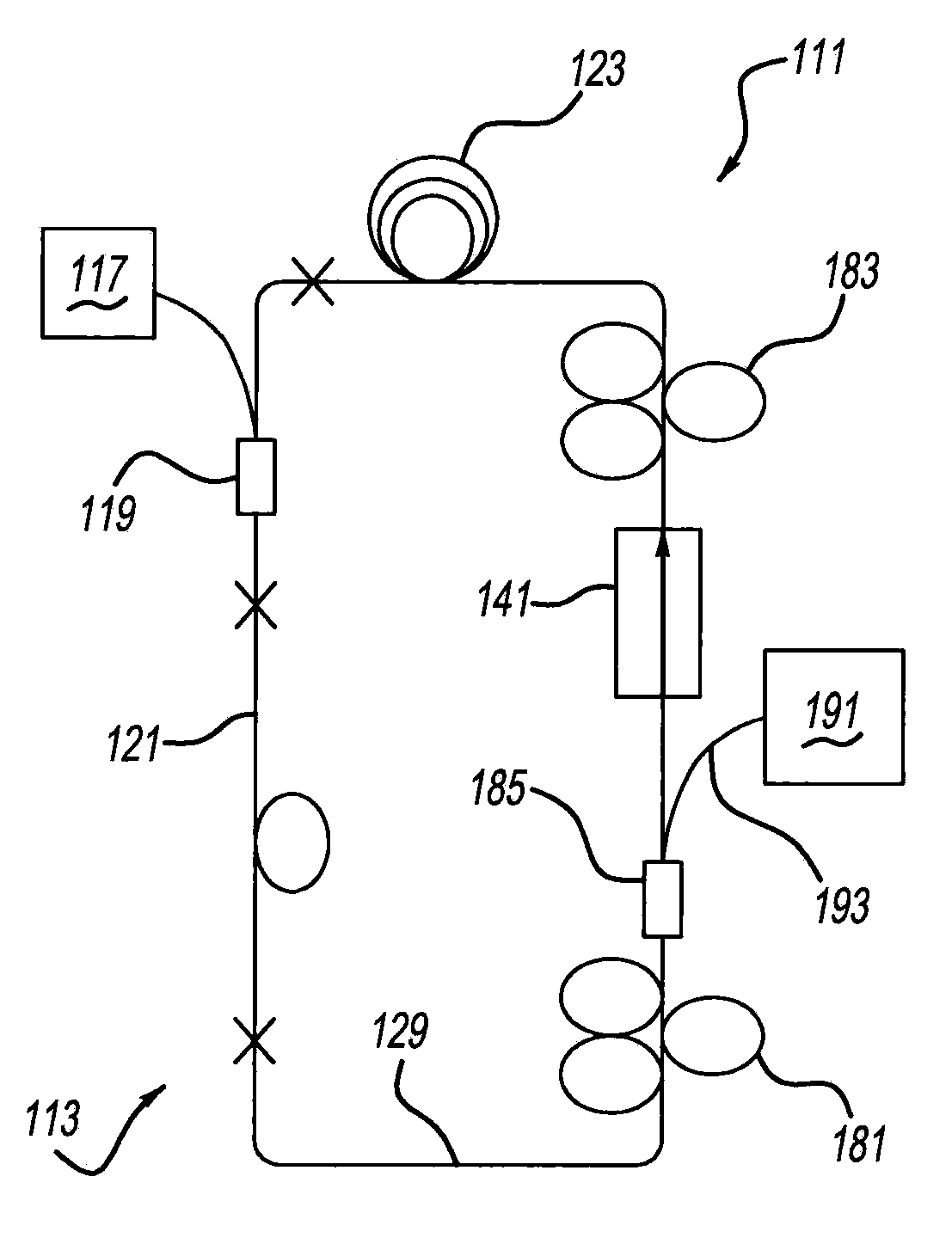
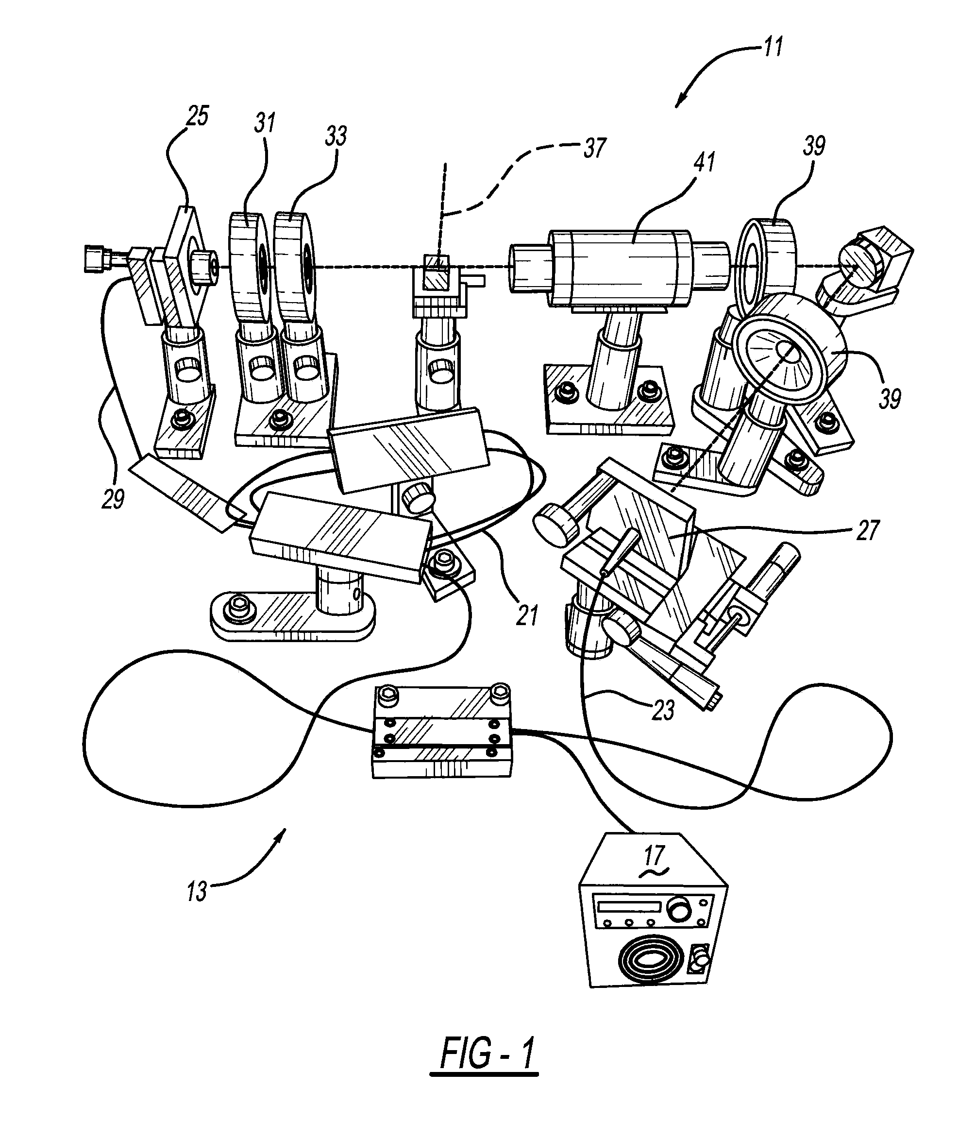
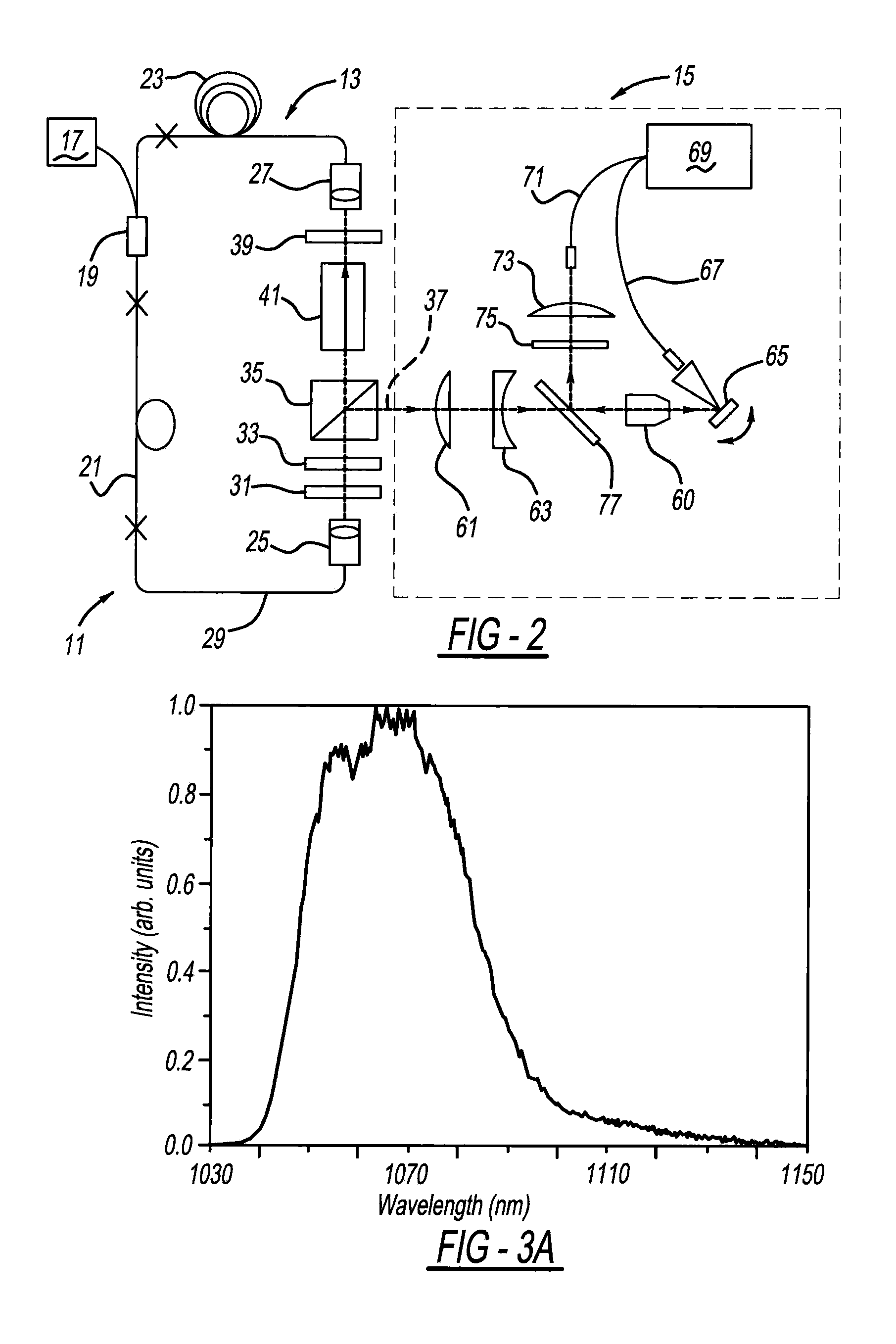
[0019]An ultrafast laser apparatus 11 is shown in FIGS. 1 and 2. Apparatus 11 includes a fiber laser oscillator 13 used with a Laser-Induced Breakdown Spectroscopy (“LIBS”) system 15. A laboratory setup of this LIBS apparatus is illustrated wherein a laser beam pulse or output is focused to form a plasma plume which atomizes a sample or specimen through surface ablation. Atomic emission lines of the specimen are then detected.

[0020]A 976 nm diode pump laser 17 emits an initial laser beam through a fiber combiner 19. An Yb doped single-mode gain fiber 21 and a passive fiber 23 are connected on either side of fiber combiner 19. Collimator 25 is connected to gain fiber 21 via a 0.35 m passive, single-mode fiber 29. A half-wave plate 31, quarter wave plate 33 and polarized beam splitter 35 are placed between collimator 25 and a laser pulse output 37. On the other side, another half wave plate 39 and an isolator 41 are located between a collimator 27 and polarized beam splitter 35. The c...


PUM


Abstract

A laser apparatus includes a fiber oscillator. In another aspect, an Ytterbium (Yb) doped fiber is employed. Another aspect provides an unamplified laser pulse emitted from an Yb fiber oscillator having a repetition rate less than 5 MHz and a pulse energy greater than 100 nJ. In still an additional aspect, a flexible Yb fiber has a length greater than 1 m which is capable of being looped with an outside loop diameter less than 150 mm. Another aspect provides for a fiber oscillator with passive optical fiber lengths of at least 10 meters, and more preferably more than 100 meters while having repetition rates less than 4 MHz.

Description

STATEMENT OF GOVERNMENT INTEREST[0001]This invention is made with government support under Grant No. NSF 1014538 awarded by the United States National Science Foundation. The government has certain rights in the invention.BACKGROUND AND SUMMARY[0002]The present invention generally relates to lasers and more particularly to a laser apparatus including a fiber oscillator.[0003]An ultrafast fiber amplifier is disclosed in U.S. Pat. No. 7,113,327 entitled “High Power Fiber Chirped Pulse Amplification System Utilizing Telecom-Type Components,” which issued to Gu et al. on Sep. 26, 2006, and is incorporated by reference herein. This system follows a traditional approach towards generating high pulse energies from fiber lasers. The guidelines being outlined in the publication of A. Galvanauskas and M. Fermann, “Hybrid Diode-Laser Fiber-Amplifier Source of High-Energy Ultrashort Pulses,”Optics Letters, Vol. 19, No. 14, 1043 (1994), state that high peak intensities inevitably lead to strong ...

Claims


Application Information

Patent Timeline
Patent Type & Authority Patents(United States)
IPC IPC(8): H01S3/067H01S3/23A61B1/00A61B18/00H01S3/16
CPCH01S3/2308H01S3/1618A61B1/00009A61B2018/00577H01S3/06704H01S3/06712H01S3/06791H01S3/094007H01S3/09415H01S3/1112H01S3/0092A61F9/008A61C1/0046A61N5/06
Inventor DANTUS, MARCOSNIE, BAI
Owner BOARD OF TRUSTEES OPERATING MICHIGAN STATE UNIV
Learn More