Eureka AIR delivers breakthrough ideas for toughest innovation challenges, trusted by R&D personnel around the world.

Two-stage single phase bi-directional PWM power converter with DC link capacitor reduction

a power converter and dc link technology, applied in the direction of electric variable regulation, process and machine control, instruments, etc., can solve the problems of reducing the potential reducing the power density of the converter, and substantial voltage ripple voltage on the dc side of the converter, so as to reduce the dc link capacitance and improve the power density. , the effect of low dc ripple voltag

Active Publication Date: 2015-06-30
VIRGINIA TECH INTPROP INC
View PDF10 Cites 18 Cited by
  • Summary
  • Abstract
  • Description
  • Claims
  • Application Information

AI Technical Summary

Benefits of technology

[0008]It is therefore an object of the present invention to provide a two-stage AC / DC bi-directional converter topology having improved power density through reduction in DC link capacitance and low DC ripple voltage with close voltage regulation while capable of rapid transient load response.
[0009]It is another object of the present invention to provide an AC / DC bidirectional power converter topology to greatly reduce the required DC link capacitance of the power converter while meeting output DC voltage and AC current regulation requirements.
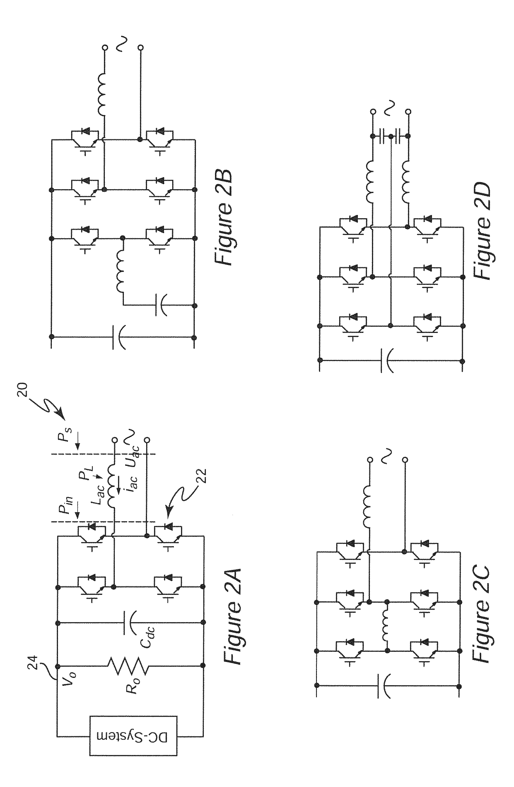
[0012]In order to accomplish these and other objects of the invention, a single-phase bi-directional AC / DC power converter is provided having a DC side and an AC side, comprising a full-bridge switching circuit connected between an AC source or load and a DC link, a DC link capacitor, and a bi-directional synchronous rectifier DC / DC power converter receiving or delivering power from or to the DC link as well as providing DC voltage regulation in one direction of power transfer and an increased DC voltage in another direction of power transfer whereby capacitance of said DC link capacitor can be reduced while limiting voltage variation at an output of said DC / DC power converter. The output of a second stage DC / DC converter maintains small DC voltage ripple allowing dramatic reduction in the DC link capacitance and overall volume reduction of the power converter.

Problems solved by technology

When power is being transferred from the AC side to the DC side, in particular, such connections cause a substantial voltage ripple voltage on the DC side of the converter which includes components at the AC line frequency and double the AC line frequency as well as high frequency components due to switching of the synchronous rectifier (SR) bridge switches.
Electrolytic capacitors of large value are also of large volume and thus greatly reduce the power density of the power converter.
Therefore, additional current limiting protection devices must be additionally provided; further reducing potential power density of the converter.
The principal drawback of this circuit is the high loss in the inductor.
A common drawback of all these approaches is the additional power loss due to the losses in the additional stage and the difficulty of linear feedback control design.
While these approaches have been somewhat successful is achieving a degree of reduction in required DC link capacitance to limit ripple voltage magnitude, the reduction has been relatively small.
Also, the performance of all of these examples are sensitive to operating conditions such as passive element values, AC side power factor angle, and the like due to the lack of robust controllers.
They also do not provide a current limit function and bi-directional operation and smooth transition between directions of power transfer has not, to the knowledge of the inventors, been documented.
Further, some current limitation is inherent in the buck converter second stage and further current limitation can be easily provided in the control arrangement for the second stage switches.
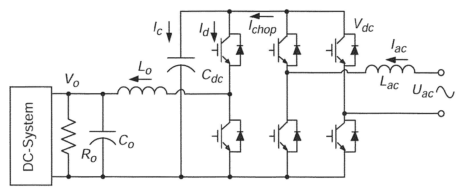
Specifically, the required DC link capacitance for a converter designed for an average DC voltage of 380 volts at 10 KW power and an inductor (Lac) value of 300 μH a switching frequency of 2π60 rad. / sec. and a 10 volt peak-to-peak ripple is 6.9 mF which generally requires a bank of electrolytic capacitors and may present a significant hazard since, as alluded to above, the circuit of FIG. 1 does not include any current limiting arrangement.
However, the reduction of DC link capacitor value, Cdc, in turn poses challenges to the controller design for separating the ripple power and DC average power, as will now be discussed.
That is, the second stage DC / DC converter voltage control loop gain at 120 Hz is not high enough to correct the output voltage ripple.
In addition, the loop-gain at 120 Hz provided by the DC link voltage controller HV is not negligibly small although insufficient to fully compensate the large voltage variation on the DC link which is the input to the second stage SR DC / DC converter.

Method used


Image

  • Two-stage single phase bi-directional PWM power converter with DC link capacitor reduction
  • Two-stage single phase bi-directional PWM power converter with DC link capacitor reduction
  • Two-stage single phase bi-directional PWM power converter with DC link capacitor reduction

Examples


Embodiment Construction

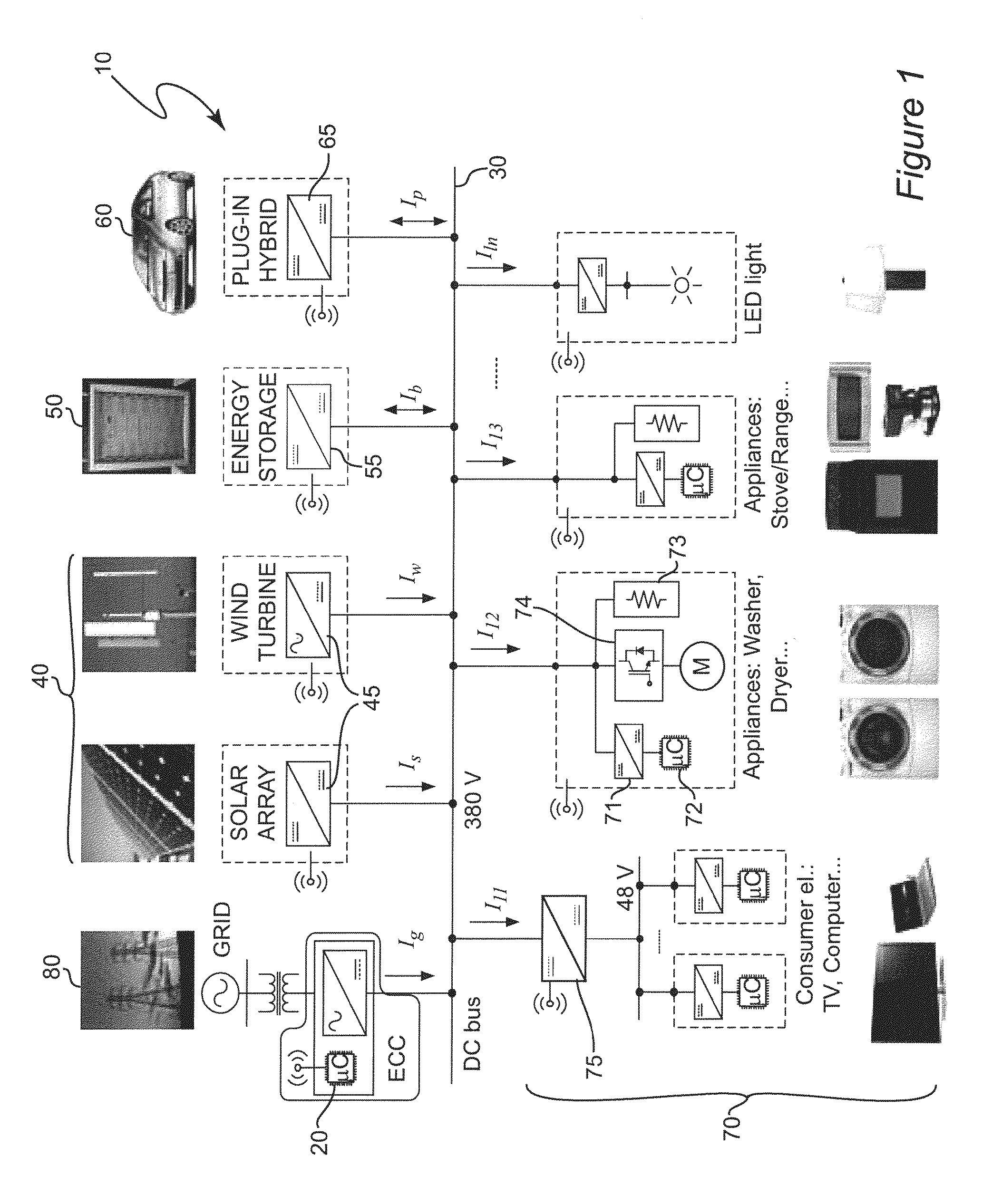
[0036]Referring now to the drawings, and more particularly to FIG. 1, there is shown, in highly schematic form, a generalized depiction of a DC nanogrid 10 which is an exemplary environment for application of the invention, generally depicted at 20. It should be understood that FIG. 1 is arranged to facilitate an understanding of the application of the invention and no portion of FIG. 1 is admitted to be prior art in regard to the present invention.

[0037]Essentially, a DC nanogrid is a power distribution grid which is generally very limited in geographic extent (e.g. limited to a building or one or a limited number of residences or a vehicle such as a ship or aircraft) in which power is distributed over DC bus 30 at a nominal DC voltage of 380 volts although other nominal voltages can be employed and, in any case, the nominal design voltage is unimportant to the successful practice of the invention. It should be understood that DC bus 30 can also be embodied as a plurality of DC bus...


PUM


Abstract

DC link capacitance in a bi-directional AC / DC power converter using a full-bridge or H-bridge switching circuit can be greatly reduced and the power density of the power converter correspondingly increased by inclusion of a bi-directional synchronous rectifier (SR) DC / DC converter as a second stage of the power converter and controlling the second stage with a control loop having a transfer function common to both buck and boost modes of operation of the bi-directional SR DC / DC converter and a resonant transfer function to increase gain at the ripple voltage frequency (twice the AC line frequency) to control the duty cycle of the switches of the bi-directional SR DC / DC stage and controlling the duty cycle of the switches of the full-bridge or H-bridge switching circuit using a control loop including a notch filter at the ripple voltage frequency.

Description

CROSS-REFERENCE TO RELATED APPLICATIONS[0001]This application claims benefit of priority of U.S. Provisional Application 61 / 473,399, filed Apr. 8, 2011, which is hereby incorporated by reference in its entirety.FIELD OF THE INVENTION[0002]The present invention generally relates to Power supplies and power converters and, more particularly, to bi-directional AC / DC power converters which are particularly useful for interfacing a DC based distribution system and / or renewable energy sources to an AC power distribution grid.BACKGROUND OF THE INVENTION[0003]At the present time, most electrical power is generated by relatively large power plants operating on fossil or nuclear fuels or hydroelectric power plants for which relatively few suitable locations exist naturally or can be developed. The distribution of such facilities and the variations in demand for power in different geographic regions requires distribution of generated alternating current (AC) power over a network of power trans...

Claims


Application Information

Patent Timeline
Patent Type & Authority Patents(United States)
IPC IPC(8): H02M7/797H02M3/158H02M7/48H02J1/10H02J3/38H02J3/32H02M1/00
CPCH02M3/1582H02M7/48H02M7/797H02J1/10H02J3/32H02M2001/007Y02B70/1425H02J3/383H02J3/386Y02E10/563Y02E10/566Y02E10/763H02J2300/40H02J2300/28H02J2300/24H02J3/381Y02B70/10Y02E10/56Y02E10/76H02M1/007
Inventor DONG, DONGBOROYEVICH, DUSHANWANG, RUXIWANG, FRED
Owner VIRGINIA TECH INTPROP INC
Why Eureka
Eureka Blog
Learn More