Method, apparatus, conduit, and composition for low thermal resistance ground heat exchange

a ground heat exchange and low thermal resistance technology, applied in indirect heat exchangers, lighting and heating apparatus, applications, etc., can solve the problems of ineffective horizontal loops, inability to use methods in urban areas, and eventually failure of metal pipe loop installations

Active Publication Date: 2015-09-01
RYGAN CORP
View PDF36 Cites 14 Cited by
  • Summary
  • Abstract
  • Description
  • Claims
  • Application Information

AI Technical Summary

Benefits of technology

[0023](c) the interior surface of the drop tube being smooth to minimize pressure drop and heat transfer along the center channel;
[0050]In another aspect, there is provided a grout composition that will not contaminate the environment.

Problems solved by technology

Experience has shown that horizontal loops are inefficient ground loops because the shallow depth of burial causes the ambient soil temperature to track the surface ground temperature.
This method can be no longer used in urban areas due to drinking water safety standards enacted to prevent aquifer contamination.
Initially, metal pipe loops were used in both concentric and U-tube installations to save capital cost, but experience has shown that metal pipe loop installations eventually fail due to anodic corrosion from conducting telluric or man-made electrical currents from one formation layer to another.
Experience has also shown that plastic ground loop installations can last indefinitely, but the local ground temperature will heat up or cool down if the seasonal load is not balanced.
Refrigerant such as Freon typically is not used due to expense and possible aquifer contamination.
This undesirable condition is known as thermal short circuit.
Prior U-tube designs have been particularly inadequate in minimizing thermal short circuit while prior concentric pipe designs have been particularly inadequate in minimizing thermal resistance of the grout and pipe wall.
U-tube designs do not have enough water storage volume or high enough pulse heat transfer to make a thermal bank.
Cost effectively manufacturing such a pipe with helical fighting disposed along the entire length of the outer surface has proven difficult and such fighting, and pipe, are easily damaged, making the flighted pipe difficult to insert into a larger diameter pipe.
Attaching the fighting as a separate piece to a smooth pipe makes the flighting susceptible to slipping along the outer surface of the pipe, which would allow the smaller diameter pipe to come in contact with the larger diameter pipe, thus creating low flow zones.
Metal pipe offers very low thermal resistance, but corrosion resistant alloys are very expensive, and their weight makes them more expensive to ship and more difficult to install.
The prior art is inadequate in providing details specifying a backfill composition that would enable sufficiently long set times for deployment and resist dissipation due to high ground water flow rates.
The design in U.S. Pat. No. 4,574,875 does not address backfill composition and the design in US Patent Application 20070029066 prefers the use of thermally conductive cement but is not specific in backfill mixture composition, nor does it address permeability, environmental safety or dissipation.
The design in U.S. Pat. No. 4,574,875 offers no solution while the design in US Patent Application 20070029066 prefers relying on laminar flow in the center channel or using an insulating gas within the smaller diameter pipe, which are both impractical solutions to implement.
The designs in both U.S. Pat. No. 4,574,875 and US Patent Application 20070029066 also fail to provide solutions that: (1) minimize pressure drop across the system; (2) prevent blockage of the center channel outlet; and (3) facilitate installation.

Method used


Image

  • Method, apparatus, conduit, and composition for low thermal resistance ground heat exchange
  • Method, apparatus, conduit, and composition for low thermal resistance ground heat exchange
  • Method, apparatus, conduit, and composition for low thermal resistance ground heat exchange

Examples


Embodiment Construction

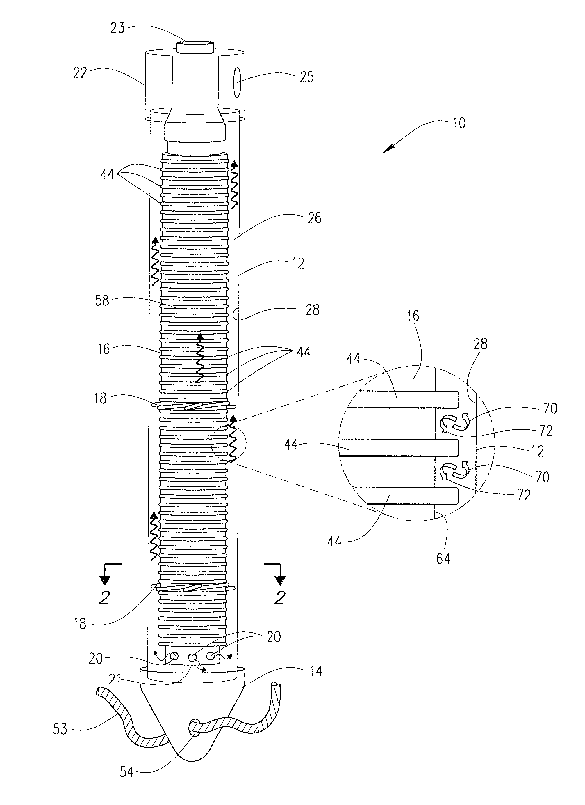
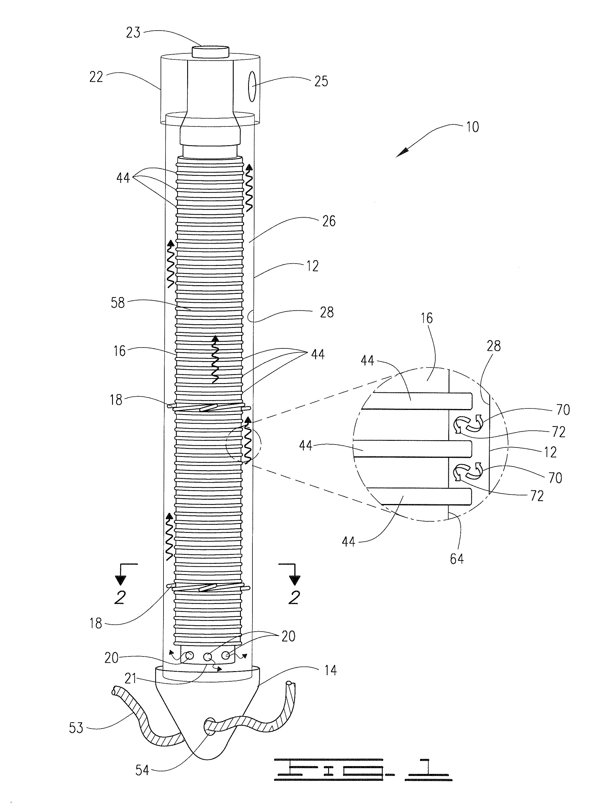
[0059]A bore 11 of desired size, preferably measuring between about 5 to about 8 inches in diameter, is drilled vertically into the earth to a depth between from about 100 to about 500′ feet. The inventive mechanical assembly 10 shown in FIGS. 1 and 2 is installed into the borehole 11 and then the borehole 11 is backfilled with an aqueous grout slurry 15 preferably comprising natural flake graphite and a binding material such as bentonite or Portland cement. Alternatively, by way of example, amorphous graphite, bentonite, and calcium sulfate could be used. As is illustrated, the pressure boundary of the mechanical assembly 10 preferably comprises an outer (i.e., a larger diameter) cylindrical casing 12 capped at the bottom by an end cap 14 and at the top by a header 22 equipped with a supply port 23 and a return port 25.

[0060]A ribbed drop tube 16 of smaller diameter is inserted inside the casing 12 and aligned concentrically with (i.e., substantially centralized in) the casing 12 t...


PUM

PropertyMeasurementUnit
collapse pressureaaaaaaaaaa
thicknessaaaaaaaaaa
specific gravityaaaaaaaaaa

Abstract

A method, apparatus, conduit, and composition for low thermal resistance ground heat exchange which preferably comprise, include, and / or use one or more of: a thin-walled, highly conductive filament wound conduit / casing formed using a thermosetting plastic composition containing a thermal conductivity enhancer; a grout backfill preferably including a sufficient amount of graphite, coke, or similar additive to provide a thermal conductivity of 3 Btu / hr-ft-° F. and higher; and a drop tube delivery conduit within the casing, the drop tube having radial exterior ribs which extend into the fluid return annulus formed between the interior wall of the casing and the exterior of the drop tube.

Description

[0001]This application claims the benefit of U.S. Provisional Patent Application Ser. No. 61 / 042,912 filed on Apr. 7, 2008 and incorporates said provisional application by reference into this document as if fully set out at this point.1. FIELD OF THE INVENTION[0002]This invention relates to the exchange of heat with the earth for heating, cooling and thermal energy storage applications. In one particular aspect, but not by way of limitation, the invention relates to cost effective materials, devices, systems, compositions, and methods which lower the thermal resistance between the working fluid of a closed loop ground heat exchanger and the earth.2. BACKGROUND OF THE INVENTION[0003]Ground heat exchangers provide more efficient heating and cooling of building spaces by exchanging heat based on the average yearly temperature of the soil and on a higher thermal conductivity of soil compared to air. The relatively constant temperature of the earth provides a more favorable temperature g...

Claims


Application Information

Patent Timeline
Patent Type & Authority Patents(United States)
IPC IPC(8): F28D7/12F28F1/42F25B49/02F28F13/00
CPCF25B49/02F28F2013/006F28D7/12F28F21/062F28F1/003F28F1/08F28F1/24F28F2240/00F28F2255/06F24T10/17Y02E10/10
Inventor FRAIM, MICHAEL
Owner RYGAN CORP
Why Eureka
Try Eureka