Plunger press and method for producing compressed bales

a technology of a plunger press and a baler, which is applied in the field of plunger presses, can solve the problems of loss of baling process, high plunger force of a single piece plunger, and considerable primary energy input, and achieve the effect of high density bales

Active Publication Date: 2015-12-08
KUHN GELDROP
View PDF9 Cites 13 Cited by
  • Summary
  • Abstract
  • Description
  • Claims
  • Application Information

AI Technical Summary

Benefits of technology

[0005]It is an object of the invention to provide a plunger press the operation of which avoids the above-mentioned drawbacks even wh...

Problems solved by technology

To achieve sufficient density in a plunger press having a one piece plunger structure requires extremely high plunger forces and considerable primary energy input.
However, the efficiency of the power input of e.g. an open channel baler plunger press is not efficient anyhow because in this type of baler not only is energy needed for compressing the material, but also for stepwise shifting the material strand after fed in material is compressed.
The energy input for shifting the material strand does not increase...

Method used


Image

  • Plunger press and method for producing compressed bales
  • Plunger press and method for producing compressed bales
  • Plunger press and method for producing compressed bales

Examples


Embodiment Construction

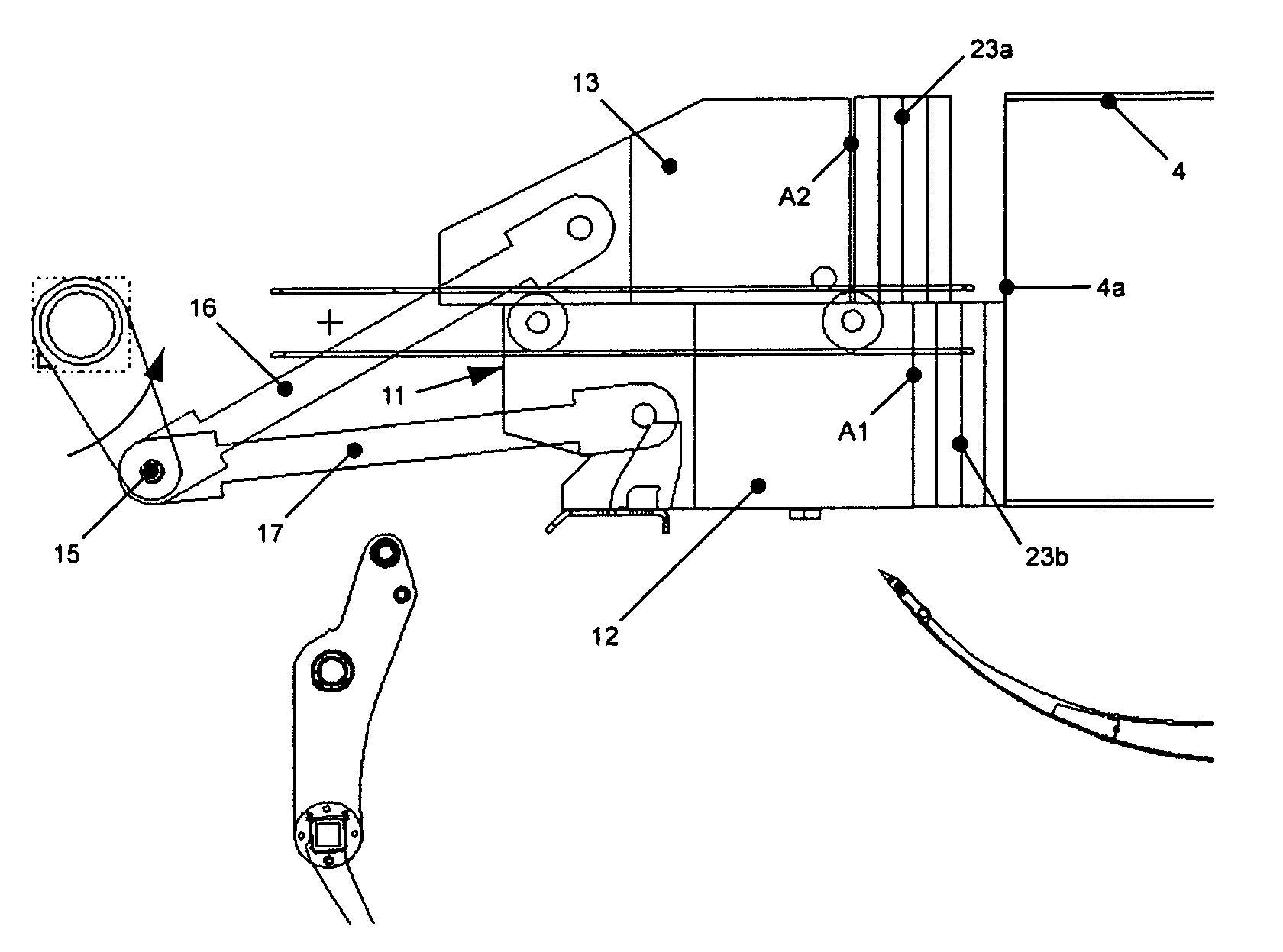
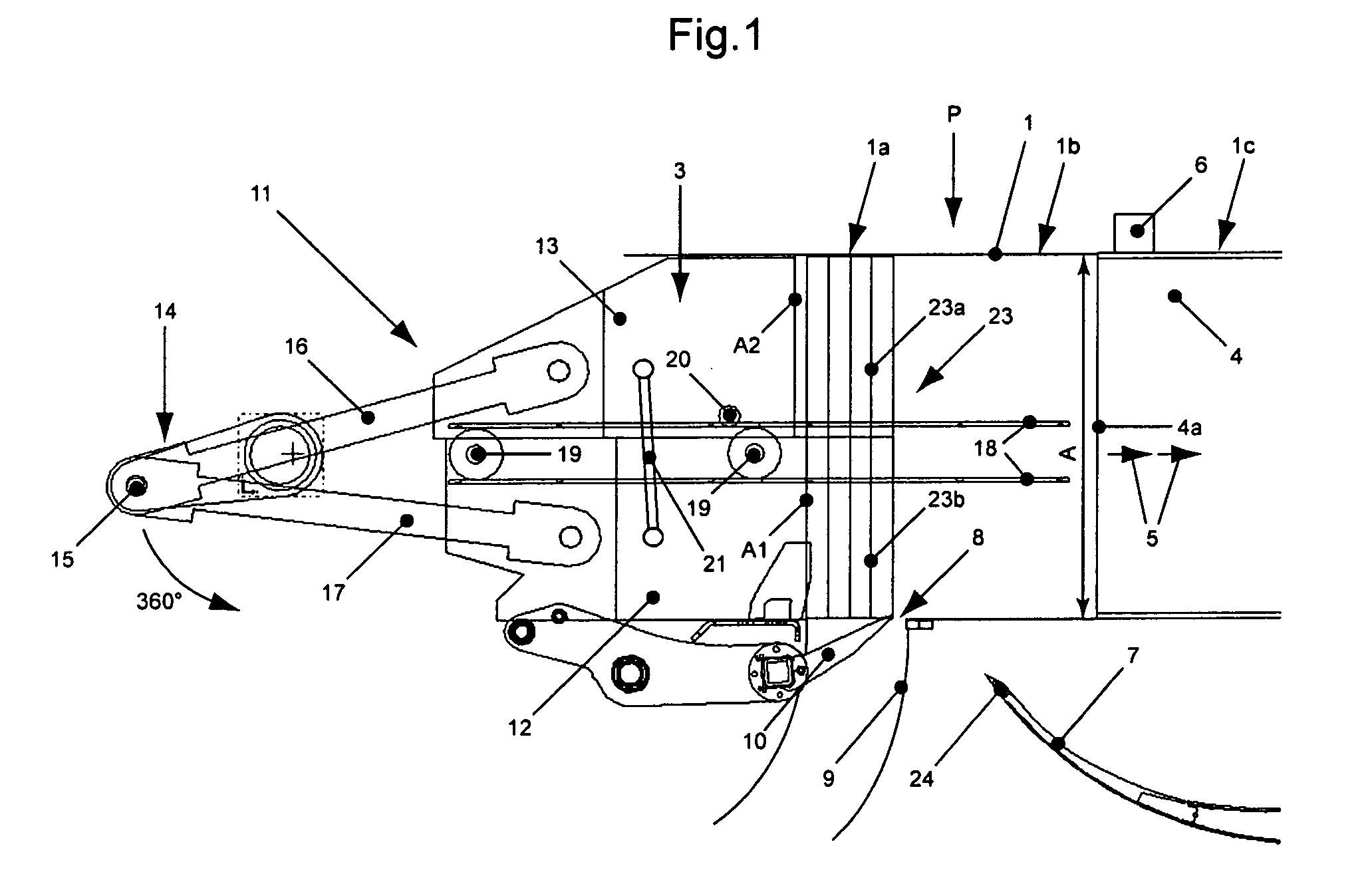
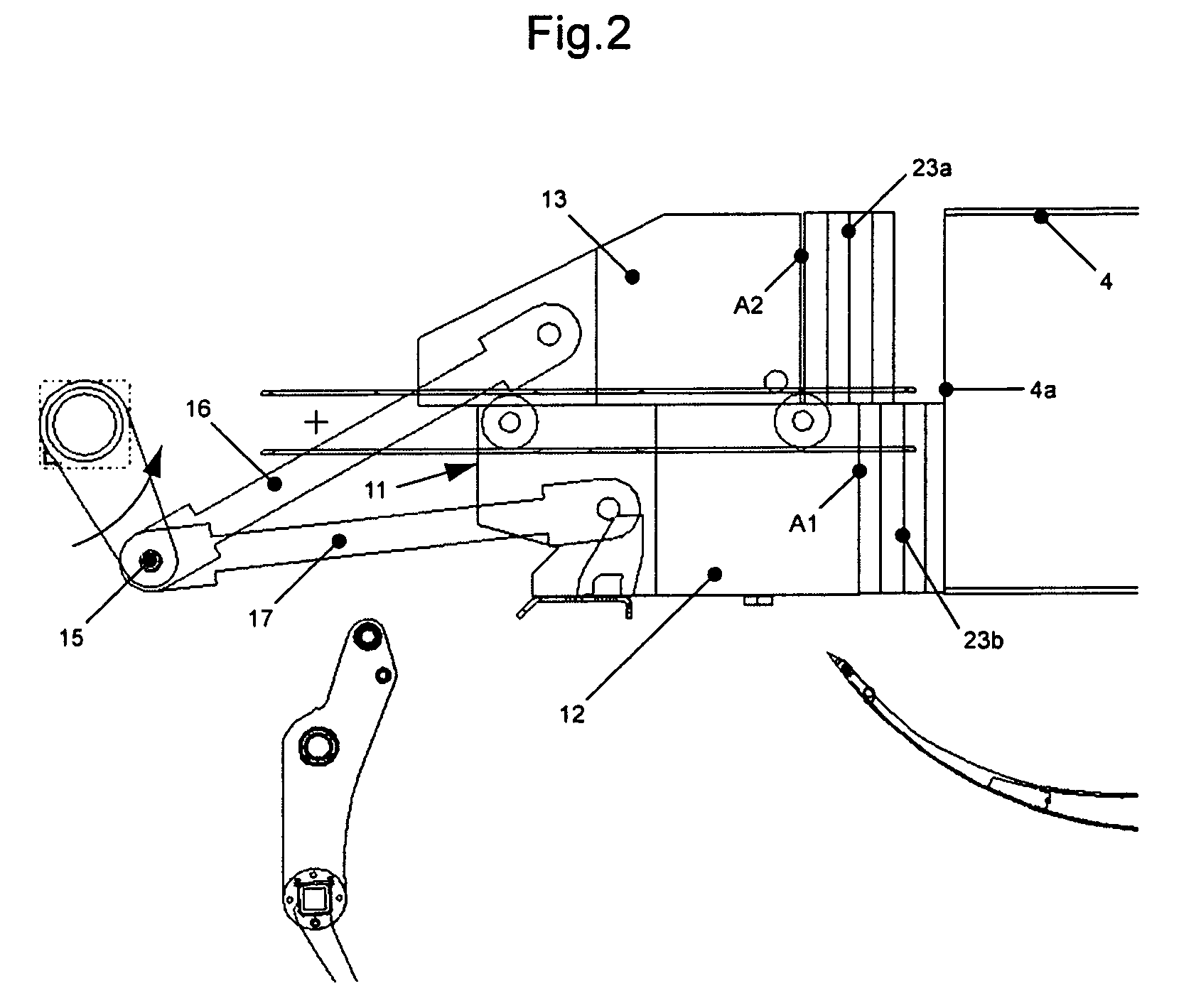
[0036]FIGS. 1 to 4 illustrate different operational phases of producing compressed bales for agricultural and / or industrial use e.g. of forage, straw, biomass or fibrous mass, in a plunger press P, being part of one open channel baler (not shown). The plunger press P has, as is conventional, a frame (not shown) encasing a bale case 1, the frame being arranged on a mobile undercarriage which is either self-propelled or is towed via a tongue coupled to a hitching device of a towing vehicle. The plunger press P is either equipped with its own drive source like a combustion engine or is supplied e.g. with e.g. hydraulic power from the towing vehicle. Alternatively, the plunger press P may be integrated into a press box baler.

[0037]A material feeding duct 9 is connected to the bale case 1, in particular to a lower side (inlet 8) of a material charge feeding section 1a which is continued in the bale case 1 to the right side in FIG. 1 by a compression section 1b and a material strand chann...


PUM


Abstract

A plunger press produces compressed bales of forage, straw, biomass or fibrous mass for agricultural and/or industrial use. The press includes a bale case, a reciprocating plunger structure, at least one material feeding duct laterally leading into a material charge feeding section of the bale case, and at least one plunger structure drive mechanism. The plunger structure compresses respective material charges fed from the feeding duct into the bale case. The plunger structure is subdivided perpendicularly to a reciprocation direction of the plunger structure in the bale case into at least two structurally separated compression surfaces. Each of the compression surfaces is smaller than a cross-section area of the bale case. The compression surfaces are driven substantially parallelly in the reciprocation direction and with a time shift in relation to each other to alternatingly compress material on partial surfaces of the cross-section area.

Description

BACKGROUND[0001]The invention relates to a plunger press and to a method 15.[0002]The plunger press of U.S. Pat. No. 4,034,543 A is an example of prior art and contains a one piece plunger structure, the active compression surface of which corresponds to the cross-section area of the bale case or the material strand in the bale case. The plunger structure compresses during each compression cycle a material charge against the end surface of the material strand. The material charge is fed laterally from the material feeding duct into the bale case while the plunger structure is retracted and against the end surface of the material strand. The plunger structure is coupled via two crank rods to a crank shaft driven via a clutch from a drive source including a fly wheel. The material charge is fed into the bale case by a pivotable feeding fork such that the material charge already is pre-compressed between the plunger structure and the material strand. Each compression cycle is carried o...

Claims


Application Information

Patent Timeline
IPC IPC(8): A01F15/04B30B9/30A01F15/08
CPCA01F15/042B30B9/3021
Inventor VAN DE LAARSCHOT, MARIJNWONDERGEM, MATTHIJS JOHANNES
Owner KUHN GELDROP
Why Eureka
Try Eureka