
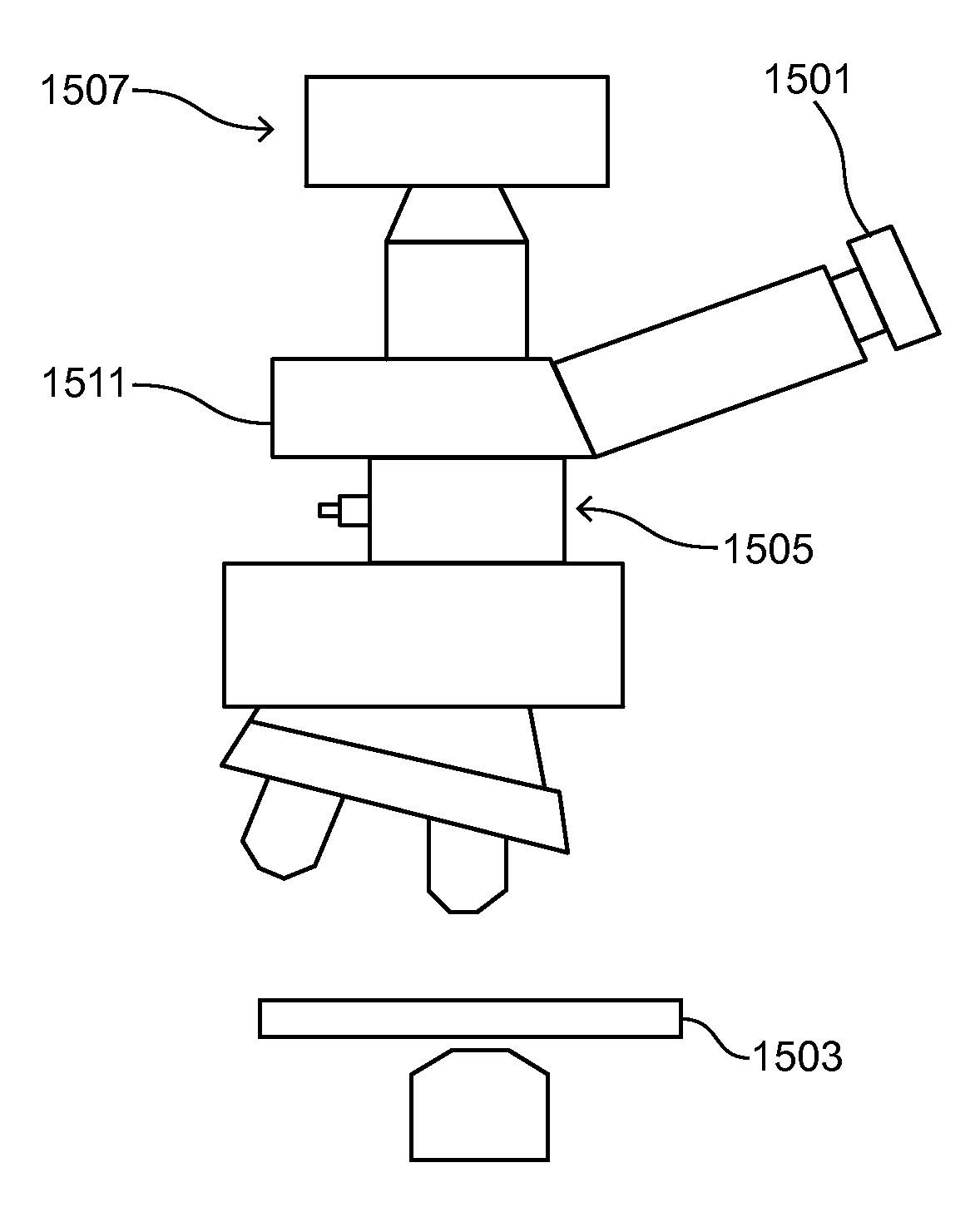
Microscope with tunable acoustic gradient index of refraction lens enabling multiple focal plan imaging

a technology of acoustic gradient index and a microscope, which is applied in the field of microscopes incorporating a tag lens, can solve the problems of thermal profile, diminishing uniformity, and few techniques for temporally modifying the beam

Active Publication Date: 2015-12-15
MITUTOYO OPTICS MFG AMERICA CORP +1
View PDF2 Cites 219 Cited by
  • Summary
  • Abstract
  • Description
  • Claims
  • Application Information

AI Technical Summary

Problems solved by technology

Industrial reliability requires uniform weld beads, but slight fluctuations in the laser, the material, or the thermal profile can diminish uniformity.
Fixed optical elements give great choice in selecting the wavefront properties of a beam of light, but there exist few techniques for modifying the beam temporally.
However, this approach suffers from a drawbacks related to large scale motion such as vibrations, repeatability and resolution.
Moreover, it can be slow and inconvenient for many industrial applications where high reliability and speed are needed.
Although current adaptive optical technologies have been successful in many applications, they suffer from limitations that prevent their use under more extreme conditions.
For instance, one of the major limitations of spatial light modulators is the slow switching speed, typically on the order of only 50-100 Hz.
Digital mirror arrays can be faster, but their cost can be prohibitive.
Also, while these devices are good for small scale applications, larger scale devices require either larger pixels, leading to pixilation errors, or they require an untenable number of pixels to cover the area, decreasing the overall speed and significantly increasing the cost.
Finally, these devices tend to have relatively low damage thresholds, making them suitable for imaging applications, but less suitable for high energy / high power laser processing.

Method used


Image

  • Microscope with tunable acoustic gradient index of refraction lens enabling multiple focal plan imaging
  • Microscope with tunable acoustic gradient index of refraction lens enabling multiple focal plan imaging
  • Microscope with tunable acoustic gradient index of refraction lens enabling multiple focal plan imaging

Examples


Embodiment Construction

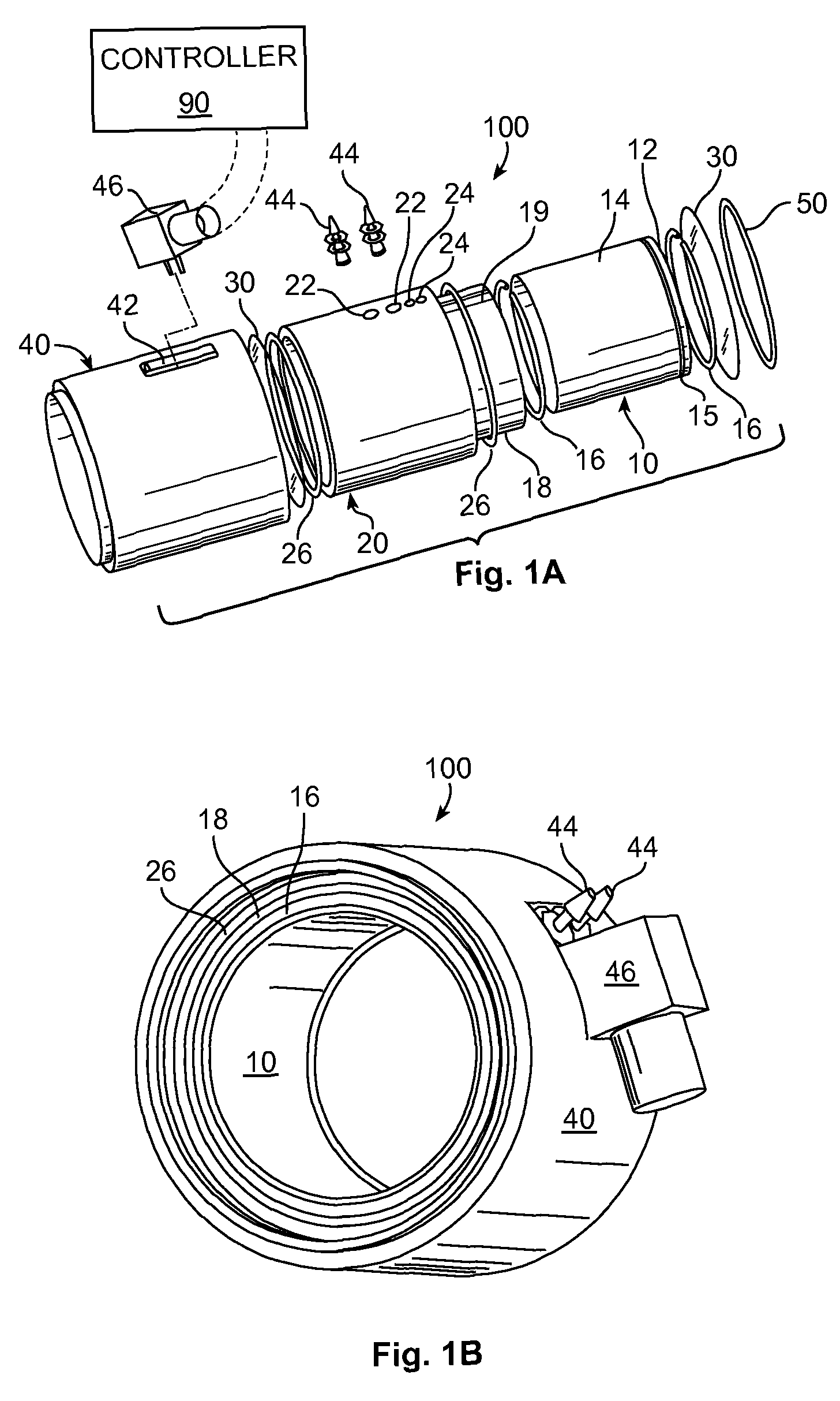
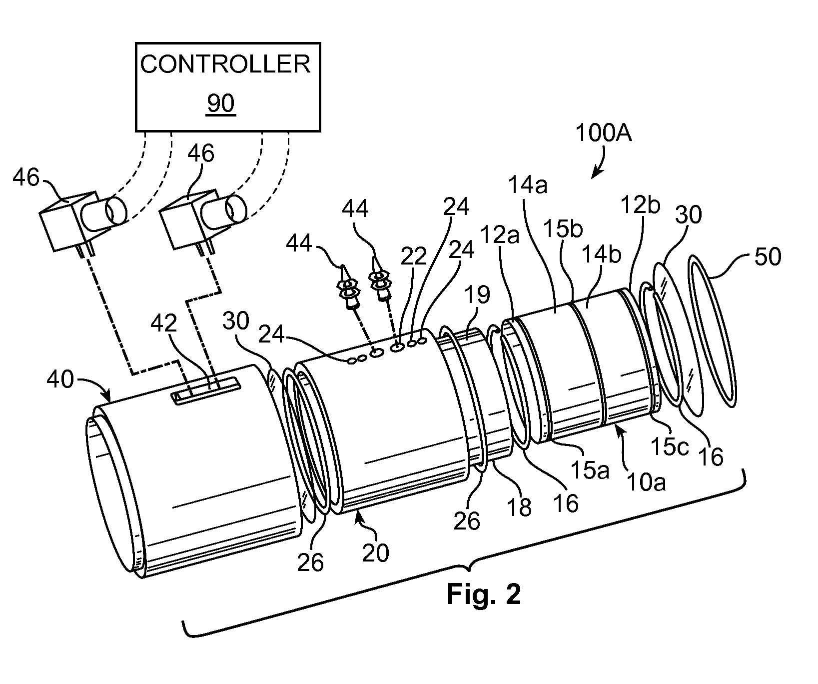
[0078]Referring now to the figures, wherein like elements are numbered alike throughout, FIGS. 1B, 1B schematically illustrates an exemplary configuration of a TAG lens 100 in accordance with the present invention having a cylindrical shape. The TAG lens 100 is a piezoelectrically driven device that uses sound waves to modulate the wavefront of an incident light beam. The lens 100 is composed of a hollow piezoelectric tube 10 that is constrained by two transparent windows 30 on either end for optical access and filled with a refractive material, such as a gas, solid, liquid, plasma, or optical gain medium, for example. The TAG lens 100 works by creating a standing acoustic wave in the refractive liquid. The acoustic standing wave is created by applying an alternating voltage, typically in the radio-frequency range, to the piezoelectric tube 10 by a controller 90. The controller 90 may include a function generator passed through an RF amplifier and impedance matching circuit.

[0079]Tu...


PUM


Abstract

An apparatus, system and method for microscopy. The apparatus, system and method includes a stage configured to receive an item; a tunable acoustic gradient index of refraction (TAG) lens having a first aspect positioned to image the received item, wherein the first aspect of the TAG lens is configured to have an optical power profile in accordance with an operational frequency of the TAG lens; one or more lenses configured to magnify an image of the received item at a viewing point; and at least one pulsed light source configured to illuminate the received item and to pulse at one or more points within the optical power profile of the TAG lens.

Description

CROSS-REFERENCE TO RELATED APPLICATION[0001]This application claims priority to U.S. Provisional Patent Application Ser. No. 61 / 552,723, filed Oct. 28, 2011, entitled Microscope with Tunable Acoustic Gradient Index of Refraction Lens Enabling Multiple Focal Plane Imaging, the entirety of which is expressly incorporated herein by reference.[0002]This application is also a continuation-in-part of U.S. patent application Ser. No. 13 / 625,285, filed Sep. 24, 2012, entitled Tunable Acoustic Gradient Index of Refraction Lens and System, U.S. patent application Ser. No. 13 / 478,314, filed May 23, 2012, entitled Tunable Acoustic Gradient Index of Refraction Lens and System, and U.S. patent application Ser. No. 13 / 473,364, filed May 16, 2012, entitled Tunable Acoustic Gradient Index of Refraction Lens and System, the entireties of which are expressly incorporated herein by reference.FIELD OF THE INVENTION[0003]The present invention relates generally to a tunable acoustic gradient index of refr...

Claims


Application Information

Patent Timeline
Patent Type & Authority Patents(United States)
IPC IPC(8): G02B21/02G02B3/00
CPCG02B21/025G02B3/0087G02F1/11G02B3/0081G02B21/06G02B25/001G02B27/0927G02F2203/18
Inventor ARNOLD, CRAIG B.
Owner MITUTOYO OPTICS MFG AMERICA CORP
Learn More