Bending insensitive single-mode optical fiber

a single-mode optical fiber, insensitive technology, applied in the direction of glass optical fiber, instruments, manufacturing tools, etc., can solve the problems of high bending stress, severe limitations of cabling indoors and in narrow environments, and high bending stress on optical fiber indoors and in narrow environments, and achieve low bending induced loss, stable mechanical performance, and effective mode field diameter and bending performance.

Active Publication Date: 2016-05-24
YANGTZE OPTICAL FIBRE & CABLE CO LTD
View PDF5 Cites 2 Cited by
  • Summary
  • Abstract
  • Description
  • Claims
  • Application Information

AI Technical Summary

Benefits of technology

[0010]The present invention relates to a bend insensitive single-mode optical fiber for solving the deficiencies in the prior art. The bend insensitive single-mode optical fiber, by optimizing an optical fiber cross-section, not only has a lower bending induced loss, stable mechanical performance, and a homogeneous material formation, but also can appropriately reduce the diameters of optical fiber's inner and trench cladding layers on the basis of keeping the diameter of the effective mode field and the bending performance, thereby lowering the fabrication cost of an optical fiber preform and an optical fiber.
[0030]The beneficial effects of the present invention lie in that: (1). By optimizing an optical fiber cross-section, the optical fiber not only has a low bending induced loss, but also has stable mechanical performance and a homogeneous material formation. (2). By optimizing the structure of an optical fiber cross-section, on the basis of keeping an effective mode field diameter and bending performance, the ratios of the core layer and the trench cladding layer in the optical fiber cross-section are reduced, so that the deposition processing amount in the most crucial, precise, and complex part in the fabrication of an optical fiber preform rod is also directly reduced, thereby lowering the control difficulty of the processes, increasing the processing efficiency of the optical fiber preform, and lowering the fabrication cost of the optical fiber. (3). The optical fiber of the present invention meets the G.657.A2 / B3 standard, while all indexes still meet the G.652.D standard, which has high compatibility with an ordinary G.652.D optical fiber and can meet the requirements for access network cabling and device miniaturization, and also, the use of the optical fiber at long wavelengths (between 1625 nm and 1675 nm) can further be ensured. Therefore, a desirable basis for large-scale application of the G.657 optical fiber is established to meet the application demands of access networks.

Problems solved by technology

An existing conventional low water peak optical fiber (meeting ITU-T G.652C / D) generally has a bend radius of 30 mm, resulting in severe limitations on cabling indoors and in narrow environments.
Compared with a long distance transmission application, optical fibers indoors and in narrow environments are subject to high bending stresses.
Especially, in use, optical fibers are often wound in storage boxes that become increasingly small, resulting in even higher bending stresses.
Nowadays, the application of the G.657 optical fiber is mainly limited by high optical fiber cost, better bending performance, and the contradiction in its compatibility with the G.652 optical fiber.
However, when a mode field diameter of an optical fiber is too small, a large connection loss occurs in its connection with a conventional single-mode optical fiber, and the incident optical power is limited.
Therefore, the space for the cut-off wavelength of the optical fiber to increase is very limited.
However, the optimized design of a depressed inner cladding layer can only improve the macro-bending performance of an optical fiber at a large bend radius to a certain extent.
When the bend radius of an optical fiber is smaller than or equal to 10 mm, it is very difficult to adopt the method of a depressed inner cladding layer to prepare a bend insensitive optical fiber that meets the G.657.A2 standard.
However, all the above patents only consider how to lower a bending induced loss and none considers a long service life of the optical fiber at a small bend radius in combination with specific applications, and also none explicitly illustrates whether an optical fiber fabricated according to the specification thereof meets or goes beyond the relevant requirement of a minimum bend radius of 5 mm in the G.657.B3 standard.
It is found through the research on an optical fiber having the structure of a trench cladding layer that certain requirements and limitations also exist about the depth and width of a trench cladding layer in the cross-section of an optical fiber: if the trench cladding layer is too shallow or too narrow, the desirable bend insensitive performance is not achieved; and if too deep or too wide, the cut-off wavelength and dispersion performance of an optical fiber might be affected.
Especially in the optical fiber design of an outer depressed cladding layer, if the depressed cladding layer is too close to the core layer, once a core layer offset occurs at an connector of an optical fiber, multi-path interferences occur easily.
If the depressed cladding layer is too far away from the core layer, the effect of lowering the bending induced loss of the optical fiber cannot be achieved.
The fabrication cost of the G.657 optical fiber is mainly affected by prices of raw materials and fabrication efficiency of equipment.
The MCVD and PCVD methods are inside deposition, and in depositing a trench cladding layer, being limited by the size of a bushing, it is usually very difficult to make the diameter of the preform to be greater than 100 mm.
Also, the inside deposition has a low rate, and the deposition thickness is too large, so that the efficiency of the equipment is obviously affected and the cost of the optical fiber is increased.
However, if a fluorine-doped cladding layer needs to be fabricated in the process of depositing a core layer and an inner cladding layer, not only the process is difficult to control, but also, in the sintering process, because of the diffusion of fluorine, it is very difficult to perform effective control on the refractive index section.
However, as both OVD and VAD are flame (H2 / O2) hydrolysis methods, when being deposited on a glass core rod, a fluorine doping layer is inevitably directly exposed in a hydrogen / oxygen flame (H2 / O2), a large number of hydroxyls generated on the H2 / O2 flame diffuse to the core layer, which causes an increase to the water peak attenuation of the drawn optical fiber.
However, once the deposited cladding layer is too thick, the formed fluorine-doped cladding layer is too far away from the core layer to exert the effect of enhancing the bending performance of the drawn optical fiber.
Also, it is very difficult to achieve deep fluorine doping in OVD and VAD processes, and also the longitudinal and axial homogeneity of the fluorine doping depth are low.
Therefore, a heretofore unaddressed need exists in the art to address the aforementioned deficiencies and inadequacies.

Method used


Image

  • Bending insensitive single-mode optical fiber
  • Bending insensitive single-mode optical fiber
  • Bending insensitive single-mode optical fiber

Examples


embodiment 1

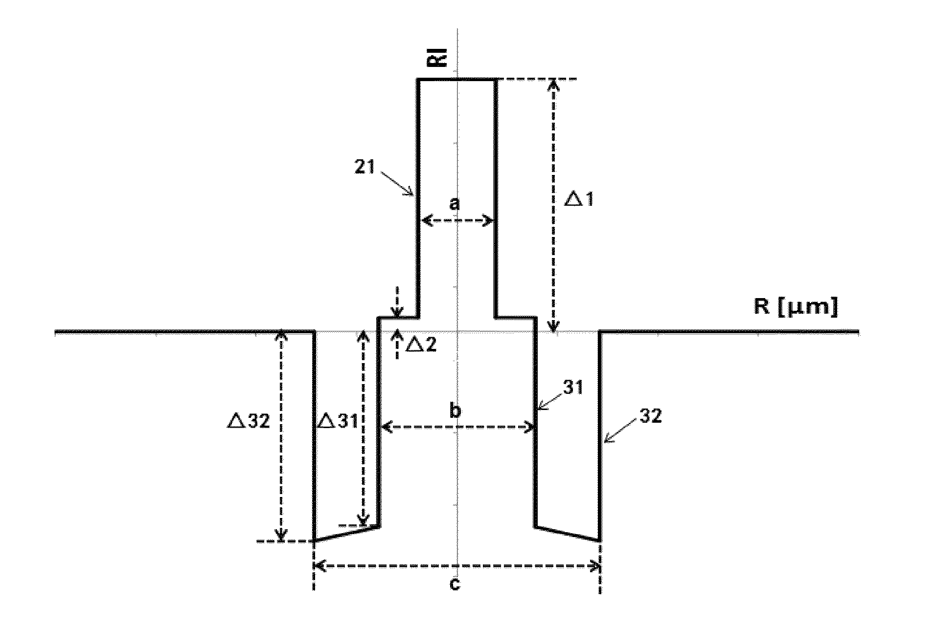
[0054]Referring to FIG. 1, the bend insensitive single-mode optical fiber in this embodiment includes a core layer and cladding layers surrounding the core layer. The cladding layers have an inner cladding layer, a trench cladding layer, and an outer cladding layer sequentially formed to cover the core layer from inside to outside. The relative refractive index difference Δ3 of the trench cladding layer changes in a gradient manner, and increases gradually from outside to inside. The relative refractive index difference Δ32 at the outermost interface 32 is smaller than the relative refractive index difference Δ31 at the innermost interface 31. The outer cladding layer surrounds the trench cladding layer. The diameter d of the outer cladding layer is about 125 μm. The refractive index of the outer cladding layer is the refractive index of pure silicon dioxide glass.

[0055]The core layer and the inner cladding layer are a germanium (Ge) and fluorine (F) doped quartz glass layer compris...

embodiment 2

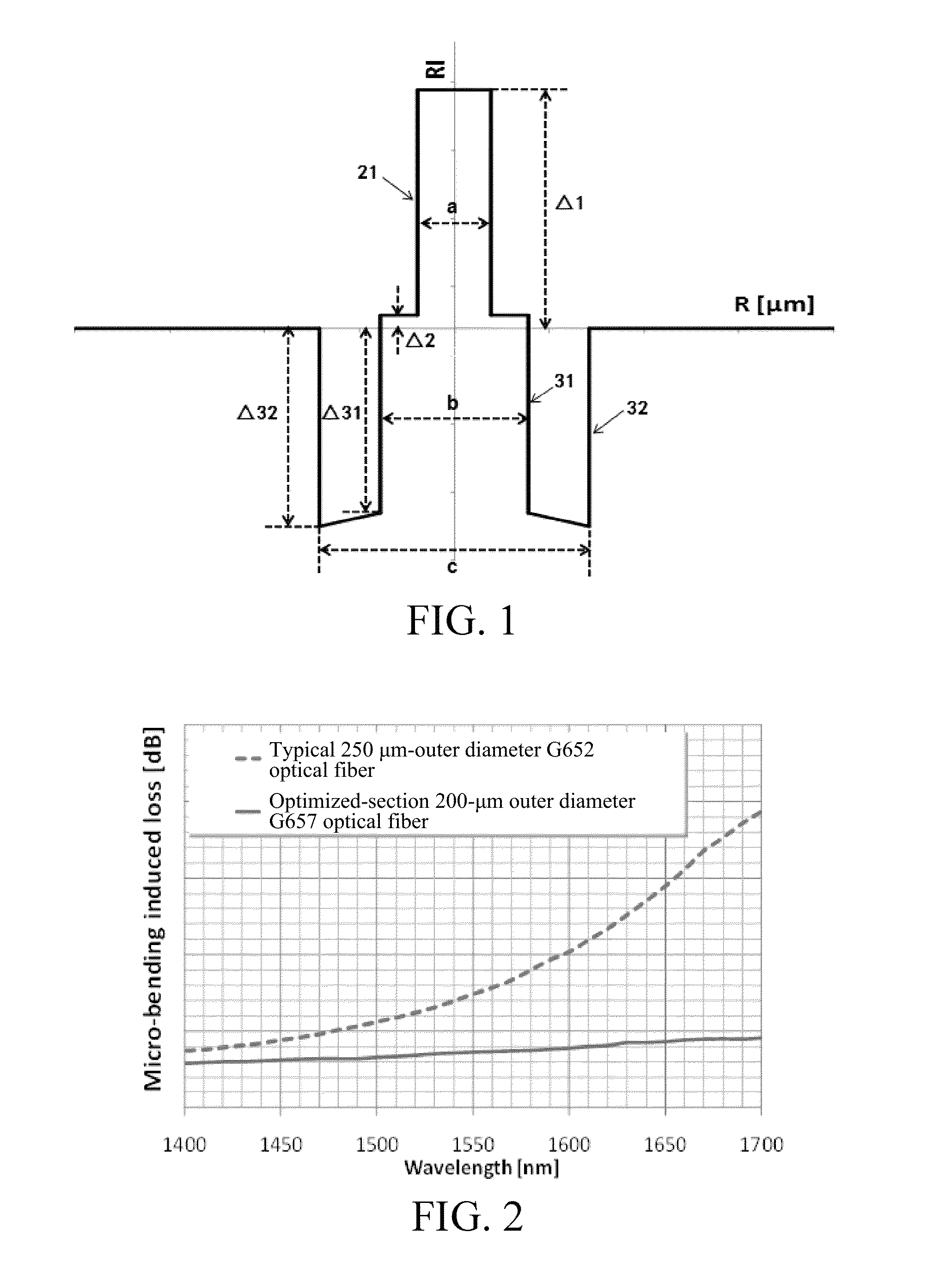
[0062]In this embodiment, the PCVD+OVD processes are adopted to prepare the G.657 optical fiber preform rod. The RIC process is adopted to perform direct drawing on the preform rod, where the drawing speed is 1500 m / min, and the fiber diameter of the naked optical fiber is 125±0.7 μm. A double-layer ultraviolet-cured optical fiber coating is adopted to apply inner and outer ultraviolet-cured polyacrylic acid resin coatings (i.e., the first and second coating layers of ultraviolet-cured polyacrylic acid resin) on the surface of the optical fiber, and after applying, the outer diameter of the optical fiber is 200±10 μm. In this embodiment, the design of the naked optical fiber section is still as shown in Embodiment 1. By optimizing the process of optical fiber application layer, a bend insensitive optical fiber with a small outer diameter is prepared. In this embodiment, the optical fiber application adopts a double-layer ultraviolet-cured acrylic ester coating, in which the first la...

embodiment 3

[0063]In the design of FTTh, as optical fibers need to pass through special bending environments such as indoor and inlet conduits and corners in the configuration process, it becomes necessary to design and fabricate a bend insensitive optical fiber having have high macro-bending performance. Based on the specifications in the ITU-T standard, the G.657.B3 optical fiber requires that on the condition of the minimum bend radius of 5 mm, at 1550 nm and 1625 nm wavelengths, the attenuation loss is smaller than 0.15 dB and 0.45 dB, respectively, so as to guarantee that the macro-bending performance of the optical fiber can meet relevant requirements of FTTh with the current FTTh optical fiber configuration conditions. As discussed above, the G.657 optical fiber can enhance the bend insensitive characteristic by adopting the method of reducing the MAC value and adopting a deep and wide depressed cladding layer, and the mode field diameter can be effectively lowered by appropriately reduc...


PUM

PropertyMeasurementUnit
diameteraaaaaaaaaa
diameteraaaaaaaaaa
diameteraaaaaaaaaa

Abstract

In one aspect of the invention, the bend insensitive single-mode optical fiber includes a core layer and cladding layers having an inner cladding layer, a trench cladding layer and an outer cladding layer sequentially formed surrounding the core layer from inside to outside. For the core layer, the diameter is 7-7.9 μm, and the relative refractive index difference Δ1 is between 4.6×10⁻³ and 6.0×10⁻³. For the inner cladding layer, the diameter is 15-17 μm, and a relative refractive index difference Δ2 is between −3×10⁻⁴ and 3×10⁻⁴. For the trench cladding layer, the diameter is 24-33 μm, and the relative refractive index difference Δ3 is between −2.9×10⁻³ and −7.3×10⁻³, changes in a gradient manner and increases gradually from outside to inside, where a relative refractive index difference Δ32 at an outermost interface is smaller than a relative refractive index difference Δ31 at an innermost interface.

Description

CROSS-REFERENCE TO RELATED APPLICATIONS[0001]This application is a continuation application of International Patent Application No. PCT / CN2012 / 086975, filed Dec. 20, 2012, which itself claims the priority to Chinese Patent Application No. 201210006783.5, filed Jan. 10, 2012 in the State Intellectual Property Office of P.R. China, which are hereby incorporated herein in their entireties by reference.[0002]Some references, if any, which may include patents, patent applications and various publications, may be cited and discussed in the description of this invention. The citation and / or discussion of such references, if any, is provided merely to clarify the description of the present invention and is not an admission that any such reference is “prior art” to the invention described herein. All references listed, cited and / or discussed in this specification are incorporated herein by reference in their entireties and to the same extent as if each reference was individually incorporated...

Claims


Application Information

Patent Timeline
Patent Type & Authority Patents(United States)
IPC IPC(8): G02B6/36G02B6/028G02B6/036G02B6/02
CPCG02B6/0365G02B6/02028G02B6/0283G02B6/02214G02B6/02395C03B37/01211C03B37/01413C03B37/01807C03B2201/12C03B2201/31C03B2203/14C03B2203/23G02B6/0286C03B37/018C03B37/027G02B6/036
Inventor ZHANG, LEIWU, YIWENGUO, HAOLINZHANG, JINYANWANG, RUICHUNMATAI, RAADJKOEMAR
Owner YANGTZE OPTICAL FIBRE & CABLE CO LTD
Why Eureka
Try Eureka