

Acoustic transducer and microphone
a transducer and microphone technology, applied in the field of acoustic transducers, can solve the problems of deteriorating sound quality, difficult to maintain sufficient quality, harmonic distortion in the output signal, etc., and achieves wide acoustic range and favorable acoustic characteristics.
- Summary
- Abstract
- Description
- Claims
- Application Information
AI Technical Summary
Benefits of technology
Problems solved by technology
Method used
Image

Examples
embodiment 1
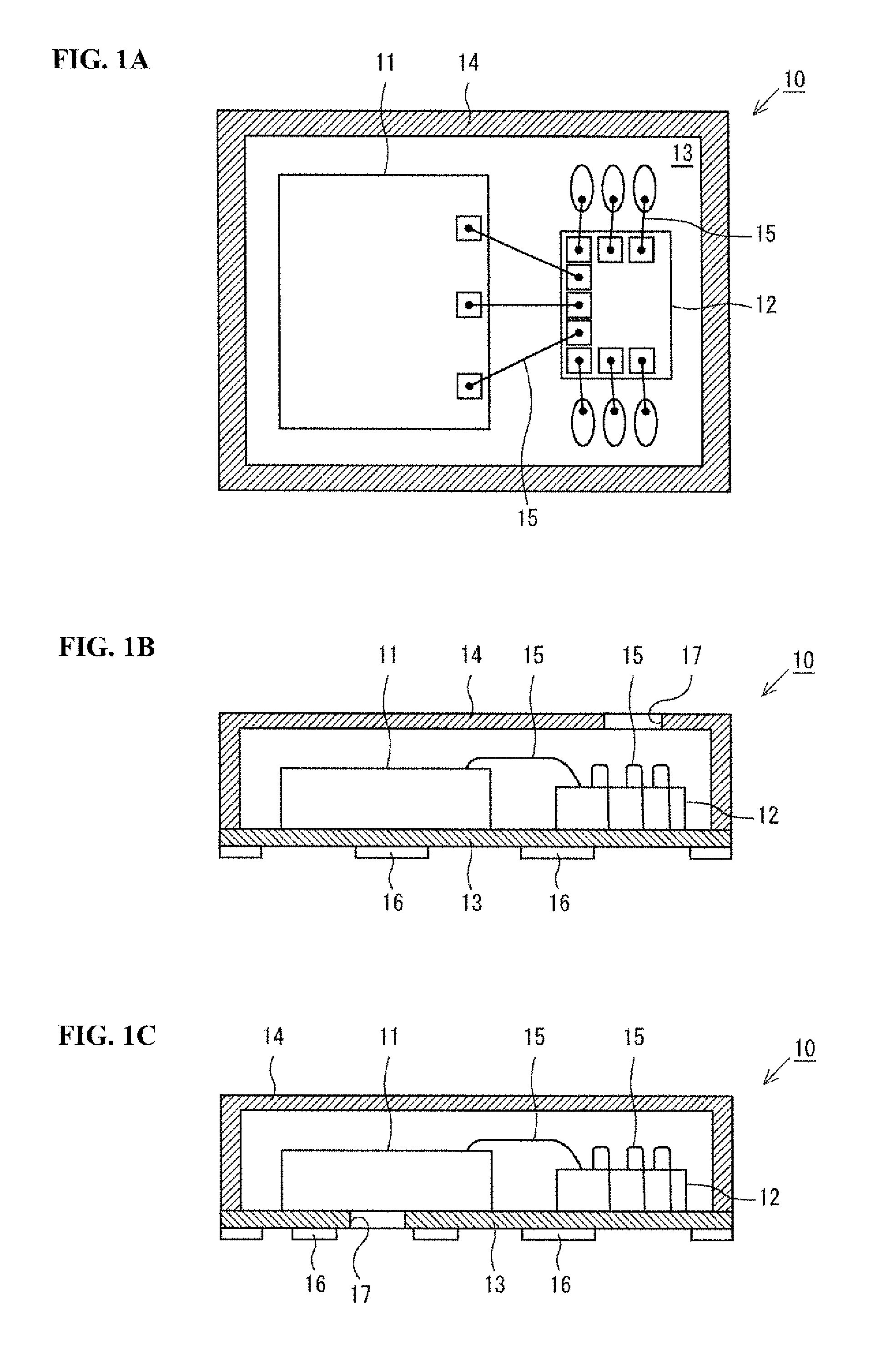
[0042]The following describes a first embodiment of the present invention with reference to FIGS. 1A to 4. FIGS. 1A to 1C show the schematic configuration of a MEMS microphone (referred to hereinafter as simply a “microphone”) 10 according to one or more embodiments of the present invention. FIG. 1A is a top view of the microphone 10, and FIGS. 16 and 1C are front views of the microphone 10. Note that FIG. 1C shows a variation of FIG. 1B. Specifically, as shown in FIGS. 1A to 1C, the microphone 10 is configured so as to include the acoustic transducer 11, an ASIC 12, an interconnect substrate 13, and a casing 14. The acoustic transducer 11 is for detecting sound waves and converting them into an electrical signal (detection signal), and is a MEMS chip manufactured using MEMS technology. Details of the acoustic transducer 11 will be described later. Also, the ASIC 12 is an IC that has a power supply function of supplying power to the acoustic transducer 11 and a signal processing fun...
embodiment 2
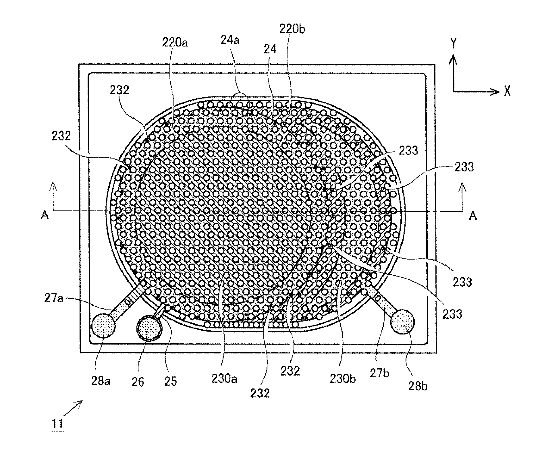
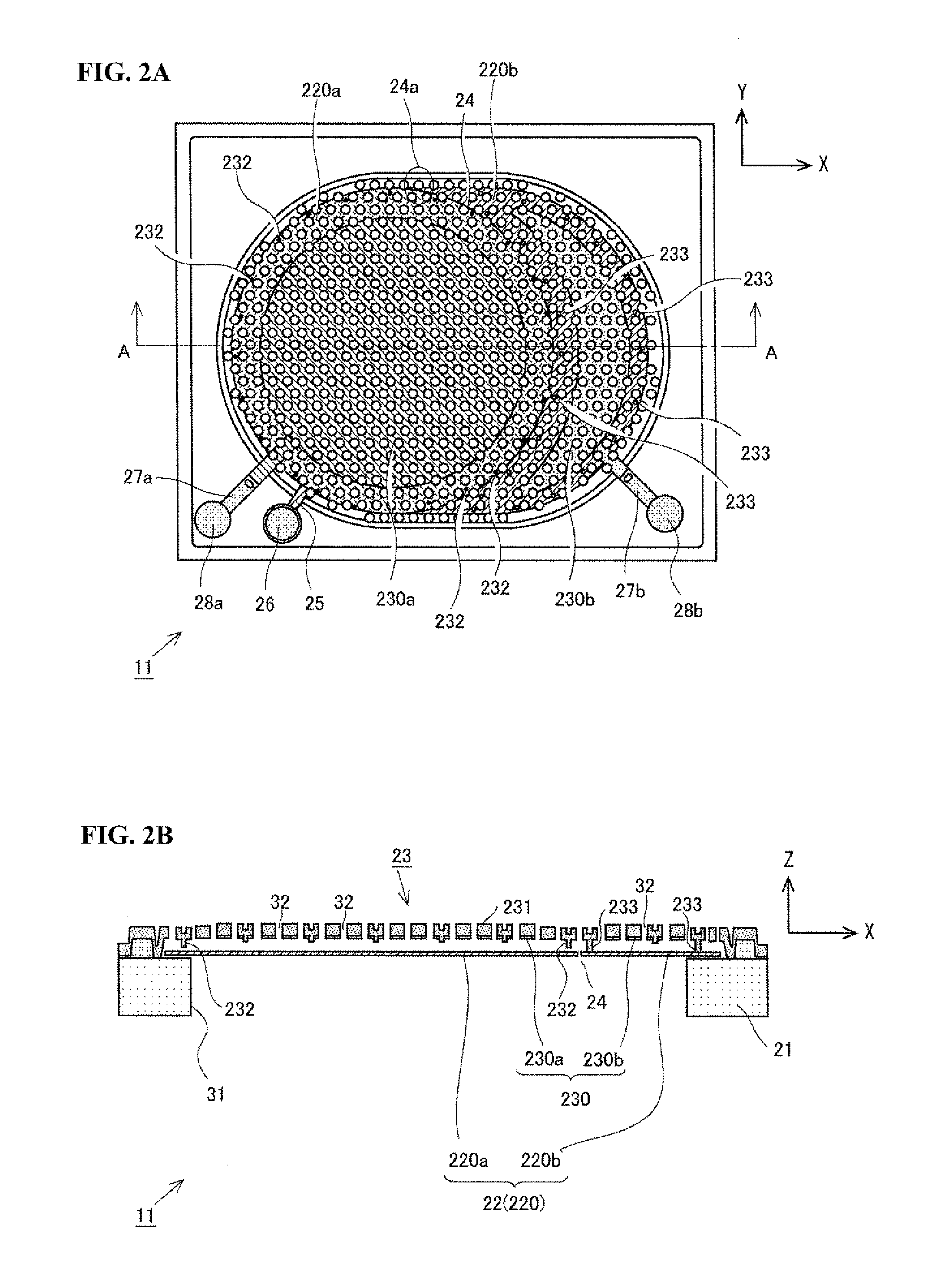
[0066]FIGS. 5A and 5B show the schematic configuration of an acoustic transducer 11 according to a second embodiment of the present invention. Note that FIG. 5A is a plan view (XY plan view), and FIG. 5B is a ZX cross-sectional diagram taken along a line A-A in FIG. 5A and viewed in the arrow direction. The acoustic transducer 11 of the second embodiment is different from the acoustic transducer of the first embodiment with respect to the configuration of the vibrating electrode 220 of the vibrating film 22 and the related configurations, and the other configurations are substantially the same. In view of this, the same reference numbers will be used for configurations that are the same, and detailed descriptions will not be given for them.
[0067]In the acoustic transducer 11 of the second embodiment, the first sensing region 220a and the second sensing region 220b of the vibrating electrode 220 are completely isolated by a space occupied by an isolation groove 24b. Specifically, in ...
embodiment 3
[0072]FIGS. 6A and 6B show the schematic configuration of an acoustic transducer 11 according to a third embodiment of the present invention. Note that FIG. 6A is a plan view (XY plan view), and FIG. 6B is a ZX cross-sectional diagram taken along a line A-A in FIG. 6A and viewed in the arrow direction. In the acoustic transducer 11 of the third embodiment, the first sensing region 220a and the second sensing region 220b of the vibrating electrode 220 are completely isolated by the space occupied by the isolation groove 24b likewise to the acoustic transducer of the second embodiment. However, the structural relationship between the fixed film 23 and the in-opening substrate portion 21b is different from the configuration in the second embodiment. In view of this, the same reference numbers will be used for configurations that are similar to those in one or more of the above embodiments, and detailed descriptions will not be given for them.
[0073]In the acoustic transducer 11 of the t...
PUM
 Abstract
Description
Claims
Application Information