Method for the brazing of parts made from a composite material, incorporating a slug in the bond

a composite material and slug technology, applied in the direction of material nanotechnology, manufacturing tools, soldering apparatus, etc., can solve the problems of insufficient breaking stress of the brazed joint, high surface roughness of the pieces made of cmc materials, and difficulty in brazing ceramic matrix composite materials together. achieve the effect of improving mechanical strength against shear forces

Active Publication Date: 2016-08-02
SAFRAN CERAMICS SA +1
View PDF9 Cites 4 Cited by
  • Summary
  • Abstract
  • Description
  • Claims
  • Application Information

AI Technical Summary

Benefits of technology

[0006]An object of the invention is to provide a method that enables composite material parts to be assembled together by brazing, but without the above-specified drawbacks, and that makes it possible in particular to make brazed connections having improved mechanical strength against shear forces.
[0013]Thus, by inserting a peg in at least one perforation present in at least one of the two composite material parts, it is possible to anchor the brazed joint securely in the material of the part and to reinforce significantly the strength of the brazed connection, in particular in shear.

Problems solved by technology

Nevertheless, brazing ceramic matrix composite materials together is technically difficult, and the breaking stress of the brazed joint is often insufficient relative to the forces to which the assembly might be subjected, in particular shear forces.
Pieces made of CMC materials present a high degree of surface roughness, which prevents the brazing composition spreading well in the zone where the brazed joint is formed, thereby creating zones of weakness in the brazed connection.
That lack of material leads to defects in the connection between the two parts, and consequently degrades the quality of the assembly by weakening the connection that is made.

Method used


Image

  • Method for the brazing of parts made from a composite material, incorporating a slug in the bond
  • Method for the brazing of parts made from a composite material, incorporating a slug in the bond
  • Method for the brazing of parts made from a composite material, incorporating a slug in the bond

Examples


Embodiment Construction

[0032]The brazing assembly method of the present invention applies to any type of thermostructural ceramic matrix composite (CMC) material, i.e. to any material made up of refractory fiber reinforcement (carbon fibers or ceramic fibers) densified by a ceramic matrix that is also refractory, such as C / SiC, SiC / SiC, C / C-SiC, etc. materials. This method also applies to other types of materials that give off gas during brazing, such as C / C materials or monolithic ceramics such as SiC, SiSiC, vitreous carbon, or pyrolytic carbon.

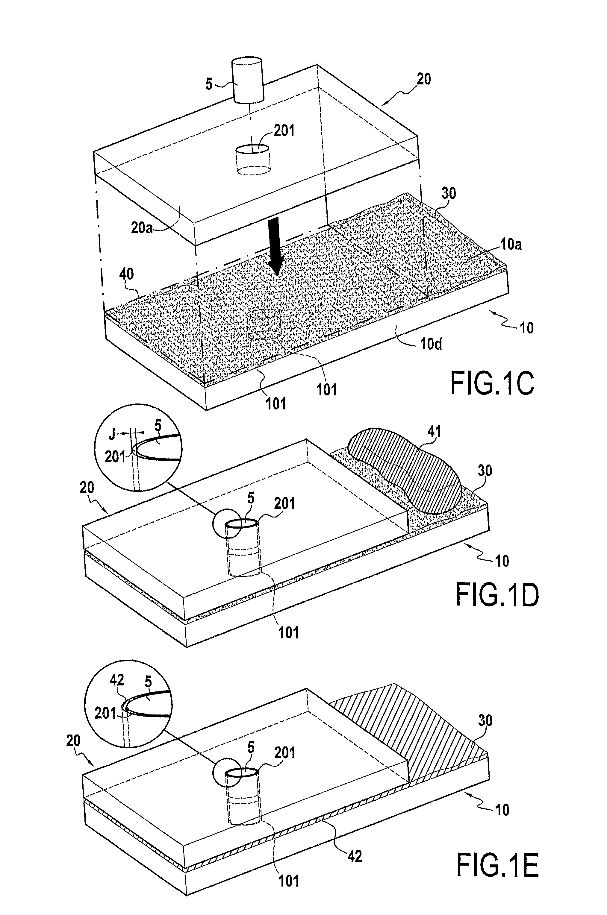
[0033]In accordance with the invention, the brazed connection formed by the method of the invention is reinforced by inserting at least one peg in a perforation made in one or both of the parts for assembling together.

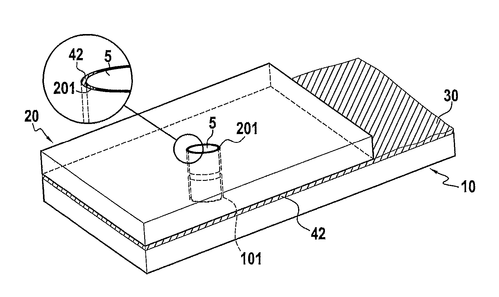
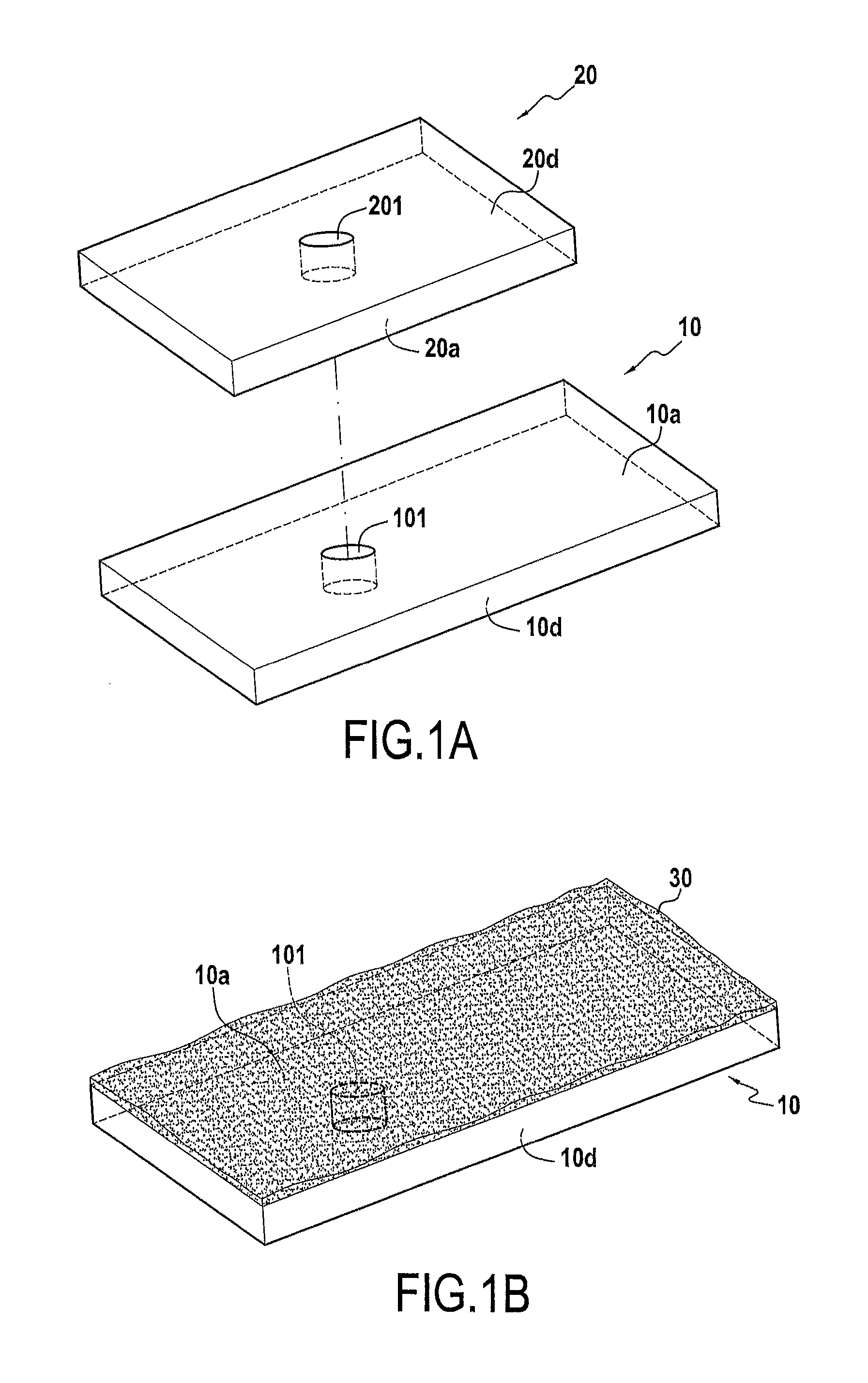
[0034]With reference to FIGS. 1A to 1E, an implementation of a method in accordance with the invention for assembling together two CMC material parts 10 and 20 by brazing comprises the following steps.

[0035]As shown in FIG. 1A, the first step consis...


PUM

PropertyMeasurementUnit
diameteraaaaaaaaaa
diameteraaaaaaaaaa
metallicaaaaaaaaaa

Abstract

A method of assembling together by brazing first and second parts made of composite material, each of the first and second parts having an assembly face for brazing with the assembly face of the other part, the method including making at least one perforation in the assembly face of the first part; interposing capillary elements between the assembly faces of the first and second parts made of composite material; placing the first and second parts facing each other while inserting a peg in each perforation of the first part; placing a brazing composition in contact with a portion of the capillary elements; and applying heat treatment to liquefy the brazing composition so as to cause the molten brazing composition to spread by capillarity between the assembly faces of the composite material parts.

Description

CROSS REFERENCE TO RELATED APPLICATIONS[0001]This application of the U.S. National Stage of PCT / FR2013 / 051672 filed Jul. 12, 2013, which in turn claims priority to French Application No. 1256949, filed Jul. 18, 2012. The contents of both applications are incorporated herein by reference in their entirety.BACKGROUND OF THE INVENTION[0002]The invention relates to using brazing to assemble together thermostructural composite materials, and in particular ceramic matrix composite (CMC) materials. CMC materials are typically formed by a porous substrate, such as a porous fiber substrate, that has been densified by a ceramic matrix. The fibers of the substrate may be made of carbon or of ceramic. By way of example, the matrix may be made of a refractory ceramic such as a refractory carbide, nitride, boride, or oxide. CMC materials, such as for example C / SiC composite materials (carbon fiber reinforcement with a silicon carbide matrix), are remarkable for their mechanical properties, which ...

Claims


Application Information

Patent Timeline
Patent Type & Authority Patents(United States)
IPC IPC(8): B23K31/02B82Y30/00C04B37/00B23K1/00B23K1/20B23K1/19
CPCC04B37/005C04B37/006B82Y30/00B23K1/0008B23K1/19B23K1/20B23K31/02C04B2235/5288C04B2235/616C04B2237/06C04B2237/062C04B2237/064C04B2237/083C04B2237/086C04B2237/12C04B2237/16C04B2237/365C04B2237/38C04B2237/385C04B2237/62C04B2237/64C04B2237/68C04B2237/84C04B2237/86B23K2001/12
Inventor REVEL, THOMASCONETE, ERICPHILIPPE, ERICROUX, GUILHEMBUCCI, PHILIPPE
Owner SAFRAN CERAMICS SA
Why Eureka
Try Eureka