Rod lens array and image sensor head that uses same

a technology of image sensor and lens array, which is applied in the field of rod lens array and image sensor, can solve the problems of difficult to achieve miniaturization of the optical system, inability to focus the image, etc., and achieve the effects of small light intensity irregularity, short conjugation, and large transmitted light amoun

Active Publication Date: 2016-09-20
MITSUBISHI CHEM CORP
View PDF11 Cites 1 Cited by
  • Summary
  • Abstract
  • Description
  • Claims
  • Application Information

AI Technical Summary

Benefits of technology

[0034]According to the present invention, it is possible to obtain a rod lens array having deep depth of focus and little depth-of-focus irregularity. In addition, according to the present invention, it is possible to obtain a rod lens array having short conjugation length, sufficiently large transmitted light amount, and little light intensity irregularity.
[0035]Furthermore, according to the present invention, it is possible to obtain an image sensor equipped with such a rod lens array that is capable of clearly reading an image even if the position of the read original shifts. Moreover, according to the present invention, it is possible to provide an image sensor for which read images are uniform and streaked unevenness is suppressed. Furthermore, since the rod lens array of the present invention can efficiently transmit the light of a light source, it can be expected to also curb electricity consumption.

Problems solved by technology

However, hand scanners, flathead-type scanners used in photocopying machines, etc. differ from facsimile machines, sheet-feed type scanners, etc., and the original document face is not fixed; therefore, the original floats during image reading, the distance between the lens surface of the rod lens and the original document face varies, and focusing the image may not be possible.
However, since the conjugation length becomes longer as the numerical aperture decreases, it becomes difficult to achieve miniaturization of the optical system.

Method used


Image

  • Rod lens array and image sensor head that uses same
  • Rod lens array and image sensor head that uses same
  • Rod lens array and image sensor head that uses same

Examples


example 1

[0180]A first layer formation stock solution (uncured form material) was made by heating and kneading 43.5 parts by mass of polymethyl methacrylate (PMMA), 15.5 parts by mass of methyl methacrylate (MMA), 7.5 parts by mass of phenyl methacrylate (PhMA), 3.5 parts by mass of t-butyl methacrylate (TBMA), 30 parts by mass of tricyclo[5.2.1.02,6]decanyl methacrylate (TCDMA), 0.25 parts by mass of 1-hydroxycyclohexyl phenyl ketone (HCPK), and 0.1 parts by mass of hydroquinone (HQ) at 70° C.

[0181]A second layer formation stock solution (uncured form material) was made by heating and kneading 44 parts by mass of PMMA, 17 parts by mass of MMA, 8 parts by mass of PhMA, 5.5 parts by mass of TBMA, 25.5 parts by mass of TCDMA, 0.25 parts by mass of HCPK, and 0.1 parts by mass of HQ at 70° C.

[0182]A third layer formation stock solution (uncured form material) was made by heating and kneading 46 parts by mass of PMMA, 16.5 parts by mass of MMA, 11 parts by mass of PhMA, 8.5 parts by mass of TBMA,...

example 2

[0203]A rod lens was prepared in the same way as Example 1 except for, after the filament after cure processing was drawn 2.34 times at 145° C., conducting relaxation processing so that the relaxation rate at 127° C. became 0.71.

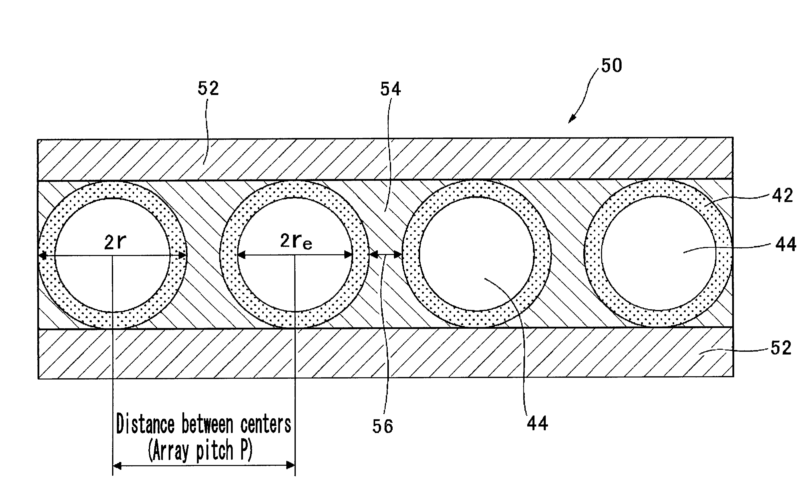
[0204]The radius r of the rod lens obtained in this way was 0.232 mm, the center refractive index n0 was 1.503 at the wavelength of 525 nm, and approximating the refractive index distribution in the range from 0.2r to 0.9r from the center to the outer periphery by a formula relating to the aforementioned refractive index distribution, the refractive index distribution constant g was 0.43 mm−1 at the wavelength of 525 nm. In addition, a layer in which dye is mixed was formed from the outer periphery towards the center, the effective radius re being 0.220 mm, and the numerical aperture NA of the lens being 0.142.

[0205]Using 684 of the obtained rod lenses, a 1-line rod lens array was prepared in which the lens length was 8.8 mm and array pitch P was 0.468 mm (g...

example 3

[0209]A rod lens was prepared in the same way as Example 1 except for, after the filament after cure processing was drawn 4.11 times at 145° C., conducting relaxation processing so that the relaxation rate at 127° C. became 0.71.

[0210]The radius r of the rod lens obtained in this way was 0.175 mm, the center refractive index n0 was 1.503 at the wavelength of 525 nm, and approximating the refractive index distribution in the range from 0.2r to 0.9r from the center to the outer periphery by a formula relating to the aforementioned refractive index distribution, the refractive index distribution constant g was 0.57 mm−1 at the wavelength of 525 nm. In addition, a layer in which dye is mixed was formed from the outer periphery towards the center, the effective radius re being 0.166 mm, and the numerical aperture NA of the lens being 0.142.

[0211]Using 914 of the obtained rod lenses, a 1-line rod lens array was prepared in which the lens length was 6.7 mm and array pitch P was 0.350 mm (g...


PUM


Abstract

The purpose of the present invention is to provide a rod lens array, which has a deep depth of focus and a small depth of focus spot. The present invention provides a rod lens array that is equipped with at least one line of rod lenses between two substrates, said line of rod lenses having a plurality of columnar rod lenses wherein the refractive index decreases toward the outer periphery from the center, said rod lenses being arranged in such a manner that the center axes of the rod lenses are substantially parallel to each other. The rod lens array is characterized in that the average value (DOFave) of the depth of focus (DOF) is at least 0.9 mm, and the depth of focus spot (DOFcv) in the scanning direction of the line of rod lenses is not more than 12%.

Description

CROSS-REFERENCE TO RELATED APPLICATIONS[0001]This Application is a U.S. National Stage Application filed under 35 U.S.C. §371 of International Application PCT / JP2013 / 058987, filed Mar. 27, 2013, designating the United States, which claims priority from Japanese Patent Application 2012-078862, filed Mar. 30, 2012, Japanese Patent Application 2012-232871, filed Oct. 22, 2012, the complete disclosures of which are hereby incorporated herein by reference in their entirety for all purposes.TECHNICAL FIELD[0002]The present invention relates to a rod lens array and an image sensor that uses the same. In more detail, the present invention relates to a rod lens array installed in an image sensor used in a flat-head-type scanner used in photocopying machines and the like, a hand scanner, etc., and an image sensor head equipped with such a rod lens array.BACKGROUND ART[0003]As one microlens, a rod lens in which both end faces of a columnar body that can be made of glass or a plastic material a...

Claims


Application Information

Patent Timeline
Patent Type & Authority Patents(United States)
IPC IPC(8): G02B3/00H01L27/146
CPCG02B3/0037G02B3/005H01L27/14627
Inventor KITAMURA, MASAFUMIIRIE, KIKUEKAWAHARADA, YASUSHI
Owner MITSUBISHI CHEM CORP
Why Eureka
Try Eureka