Hybrid high electron mobility transistor and active matrix structure

a high electron mobility, active matrix technology, applied in the direction of electroluminescent light sources, electric lighting sources, semiconductor lamp usage, etc., can solve the problem of too low carrier mobility of a-si:h (electron mobility of about 1 cmsup>2, ns) to provide sufficient drive current at short tft channel widths, and increase the processing cost of a-si:h active matrix circuits

Inactive Publication Date: 2016-11-22
IBM CORP
View PDF16 Cites 13 Cited by
  • Summary
  • Abstract
  • Description
  • Claims
  • Application Information

AI Technical Summary

Benefits of technology

[0011]Substantial beneficial technical effects are provided by the exemplary structures and methods disclosed herein. For example, one or more embodiments may provide one or more of the following advantages:[0012]Enabling higher resolution displays due to relatively high drive current and / or low operation voltage compared to a-Si:H or organic TFTs;[0013]Same fabrication infrastructure for backplane and frontplane structures feasible;[0014]Low-temperature processing compatible with flexible and low-cost substrates;[0015]Larger minimum device feature size (channel length) compared to a-Si:H devices allowing lower lithography costs.[0016]Lower power consumption compared to a-Si:H or organic TFT backplanes due to lower operation voltages.
[0012]Enabling higher resolution displays due to relatively high drive current and / or low operation voltage compared to a-Si:H or organic TFTs;
[0015]Larger minimum device feature size (channel length) compared to a-Si:H devices allowing lower lithography costs.
[0016]Lower power consumption compared to a-Si:H or organic TFT backplanes due to lower operation voltages.

Problems solved by technology

However, for very high resolution applications (>1000 pixels per inch (ppi)), such as micro-displays or pico-projectors, the carrier mobility of a-Si:H (electron mobility of about 1 cm2Ns) is too low to provide sufficient drive current at short TFT channel widths.
This leads to increasing the processing cost of a-Si:H active matrix circuits due to the relatively small gate lengths as well as a significant trade-off in display resolution due to larger gate widths.
The device-to-device variation of threshold voltage and mobility in LTPS transistors requires compensation circuitry that limits the resolution of the active matrix.
Using such TFTs, resolutions greater than 150 PPI are difficult.

Method used


Image

  • Hybrid high electron mobility transistor and active matrix structure
  • Hybrid high electron mobility transistor and active matrix structure
  • Hybrid high electron mobility transistor and active matrix structure

Examples


Embodiment Construction

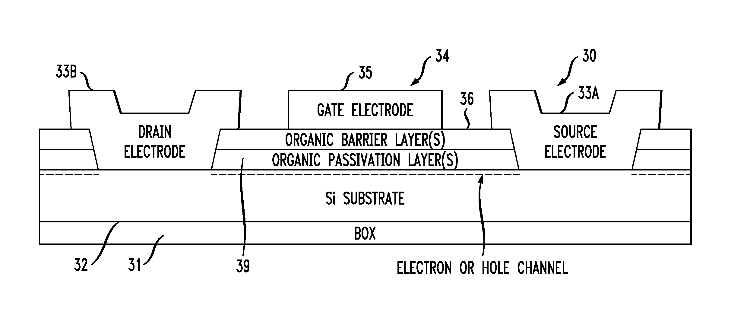
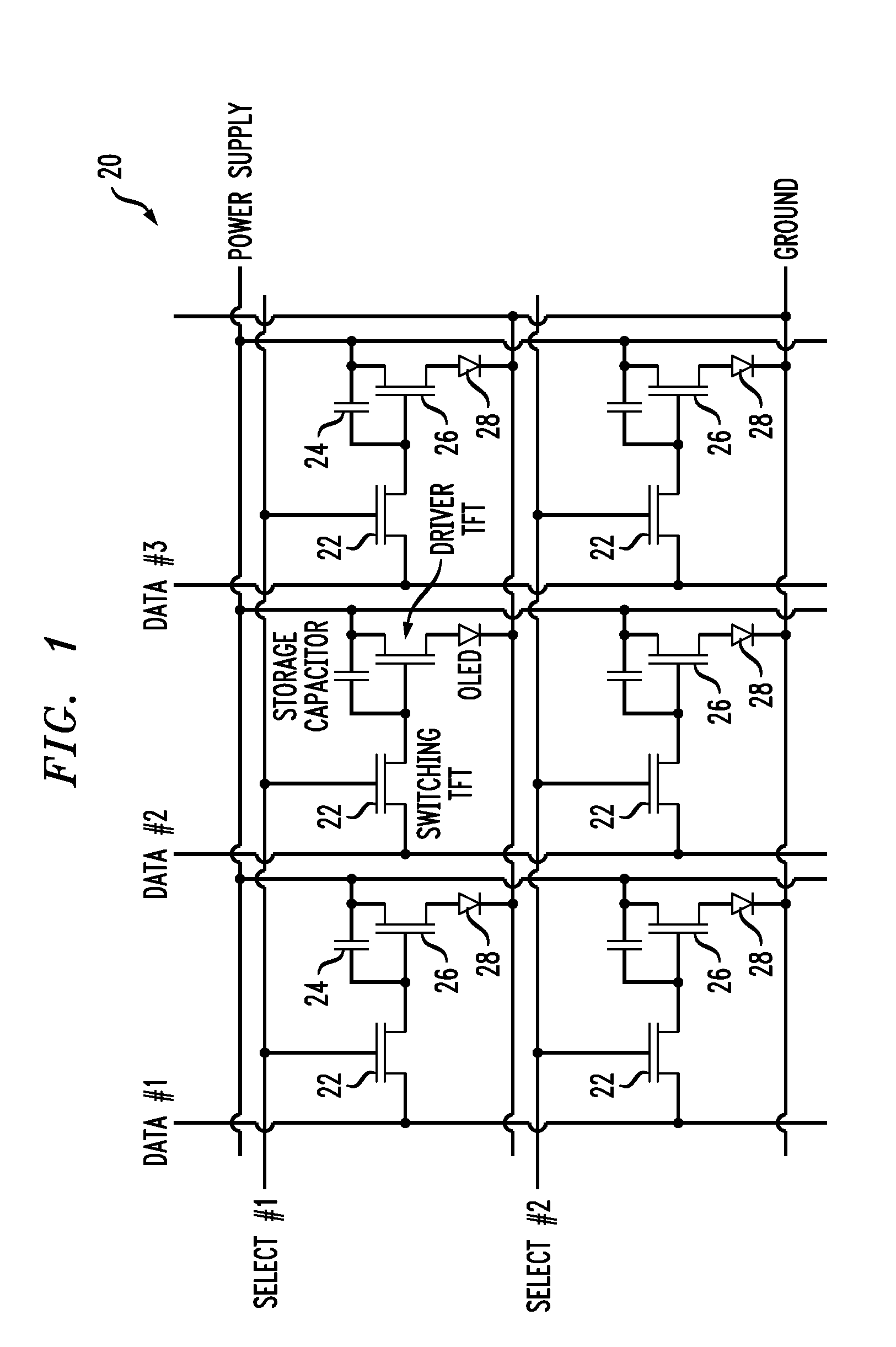
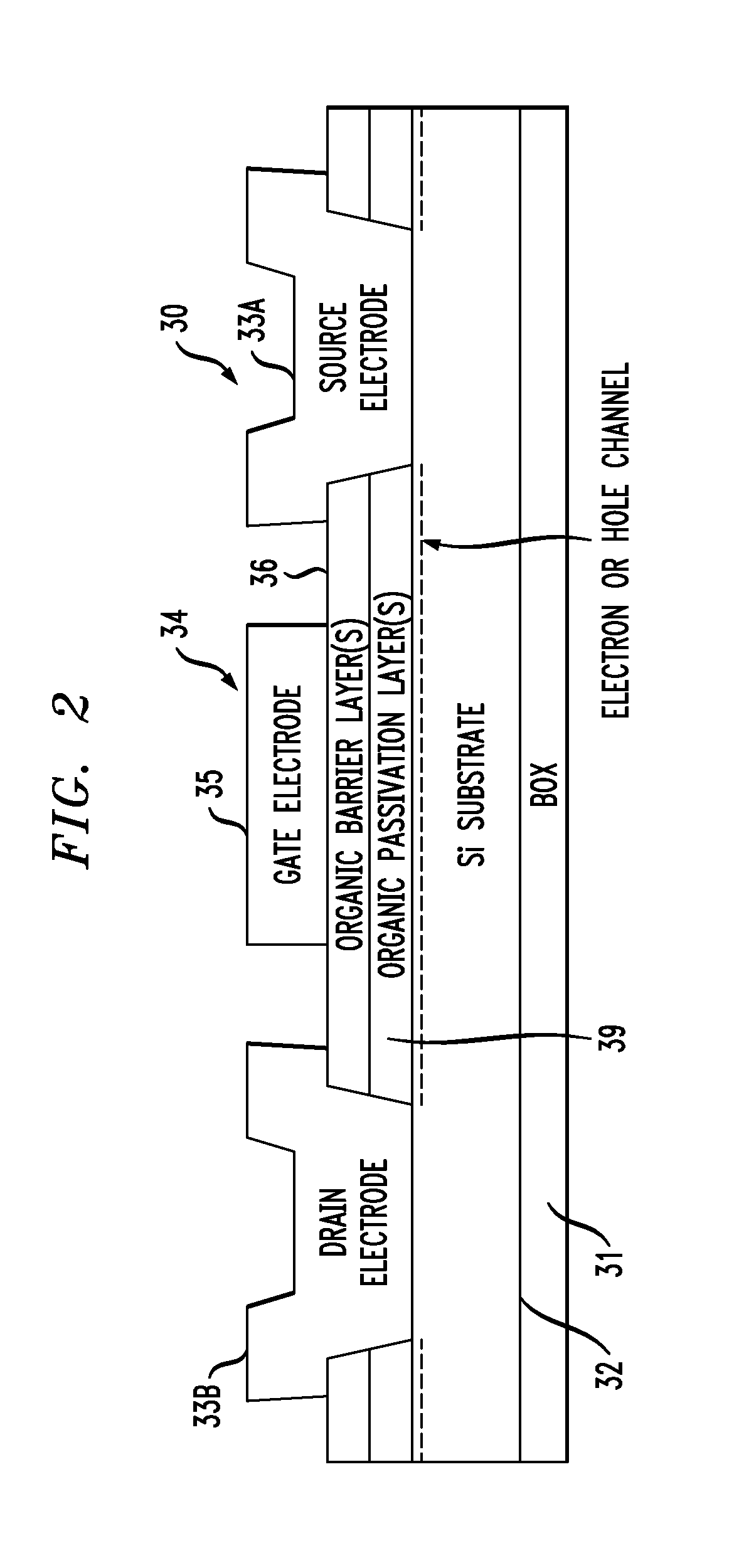
[0036]Thin-film hybrid high electron mobility transistors (HEMTs) are disclosed that include crystalline, inorganic semiconductor channels and organic gate barrier layers. Such transistors are used in some embodiments for forming high resolution active matrix displays. A backplane refers to an array of transistors (active devices) used for addressing and programming passive devices such as light emitting diodes, liquid crystal displays, photosensitive materials (e.g. for x-ray imaging), or sensors (e.g. piezoelectric materials for sensing pressure). The backplane also contains address lines, program lines, power supply lines, and typically storage capacitors which are fabricated using the same process technology as that of the transistors. Arrays of passive devices addressed / programmed by the backplane are typically referred to as the frontplane. An active matrix refers to the combination of a backplane and a frontplane. Schematic pixel circuits of active-matrix arrays comprised of ...


PUM


Abstract

Hybrid high electron mobility field-effect transistors including inorganic channels and organic gate barrier layers are used in some applications for forming high resolution active matrix displays. Arrays of such high electron mobility field-effect transistors are electrically connected to thin film switching transistors and provide high drive currents for passive devices such as organic light emitting diodes. The organic gate barrier layers are operative to suppress both electron and hole transport between the inorganic channel layer and the gate electrodes of the high electron mobility field-effect transistors.

Description

FIELD[0001]The present disclosure relates to thin-film electronic device structures and technology and, more particularly, to high electron mobility transistors, active matrix structures such as backplanes incorporating such transistors, and the fabrication of high electron mobility transistors and active matrix structures using both inorganic and organic materials.BACKGROUND[0002]Field-effect transistors include source, drain and gate structures. A biasing voltage applied across gate and source terminals allows the flow of charge carriers, namely electrons or holes, between source and drain. High electron mobility transistors (HEMTs) are characterized by heterojunctions having different materials on either side of the junctions. Electrons remain close to the heterojunction and form two dimensional electron gas (2DEG). A bias applied to the gate modulates the number of electrons and controls the conductivity of the transistor.[0003]Active matrix devices such as displays (e.g. televi...

Claims


Application Information

Patent Timeline
Patent Type & Authority Patents(United States)
IPC IPC(8): H01L27/12H01L29/43H01L29/778H01L29/40H01L29/66H05B44/00
CPCH01L27/1214H01L29/408H01L29/435H01L29/66431H01L29/7786H01L29/432H01L29/778H01L29/4908H01L27/0688H01L29/78696H01L27/1207H01L21/8221H01L27/1251H01L27/1218H01L27/1225H01L29/78603H01L29/78654H05B45/60Y02B20/30H05B47/165H10K59/12H10K10/486H10K10/29H10K10/46H10K10/84H10K10/88H10K10/464H10K10/474H10K10/484H10K19/20H10K59/125
Inventor AFZALI-ARDAKANI, ALIHEKMATSHOARTABARI, BAHMANSADANA, DEVENDRA K.SHAHRJERDI, DAVOOD
Owner IBM CORP
Why Eureka
Try Eureka