Method of and apparatus for combusting sulfurous fuel in a circulating fluidized bed boiler

a fluidized bed and boiler technology, applied in the direction of combustion types, emissions prevention, separation processes, etc., can solve the problems of reducing the thermal affecting the combustion efficiency of the boiler, so as to reduce the relative amount of material, reduce the effect of lime content of coarse and finest bottom ash portions, and reduce the potential for causing

Active Publication Date: 2017-02-28
AMEC FOSTER WHEELER ENERGIA
View PDF15 Cites 2 Cited by
  • Summary
  • Abstract
  • Description
  • Claims
  • Application Information

AI Technical Summary

Benefits of technology

[0020]The classifying of the bottom ash in the first stage and the second stage classifiers is performed by any suitable equipment, such as a centrifugal separator, an air classifier, or a sieve. During the first stage classifying, i.e., during the classifying in the first stage classifier, the largest particles, which have a high potential for causing abrasion and erosion of any downstream equipment, are separated from the finer bottom ash portion. A special advantage of the first stage classifying is that by removing the largest particles, the relative amount of silicates, e.g., sand or SiO2, and Fe2O3 in the finer bottom ash portion is reduced. A special advantage of the second stage classifying is that by removing the smallest particles, the relative amount of the product, e.g., CaSO4 in the finer bottom ash is reduced. The classifying is thus especially advantageous, because it decreases the relative amount of material that is inert for SO2 removal.
[0021]On the other hand, during

Problems solved by technology

When combusting sulfur-containing fuels, the sulfur in the fuel is converted to sulfur oxides, mainly, sulfur dioxide, which may be harmful if emitted to the environment in large quantities.
When using high Ca/S ratios, such as from four to five, the bottom ash and fly ash discharged from the furnace invariably contain a large amount of CaO, typically, from about 10% to mo

Method used


Image

  • Method of and apparatus for combusting sulfurous fuel in a circulating fluidized bed boiler
  • Method of and apparatus for combusting sulfurous fuel in a circulating fluidized bed boiler
  • Method of and apparatus for combusting sulfurous fuel in a circulating fluidized bed boiler

Examples


Embodiment Construction

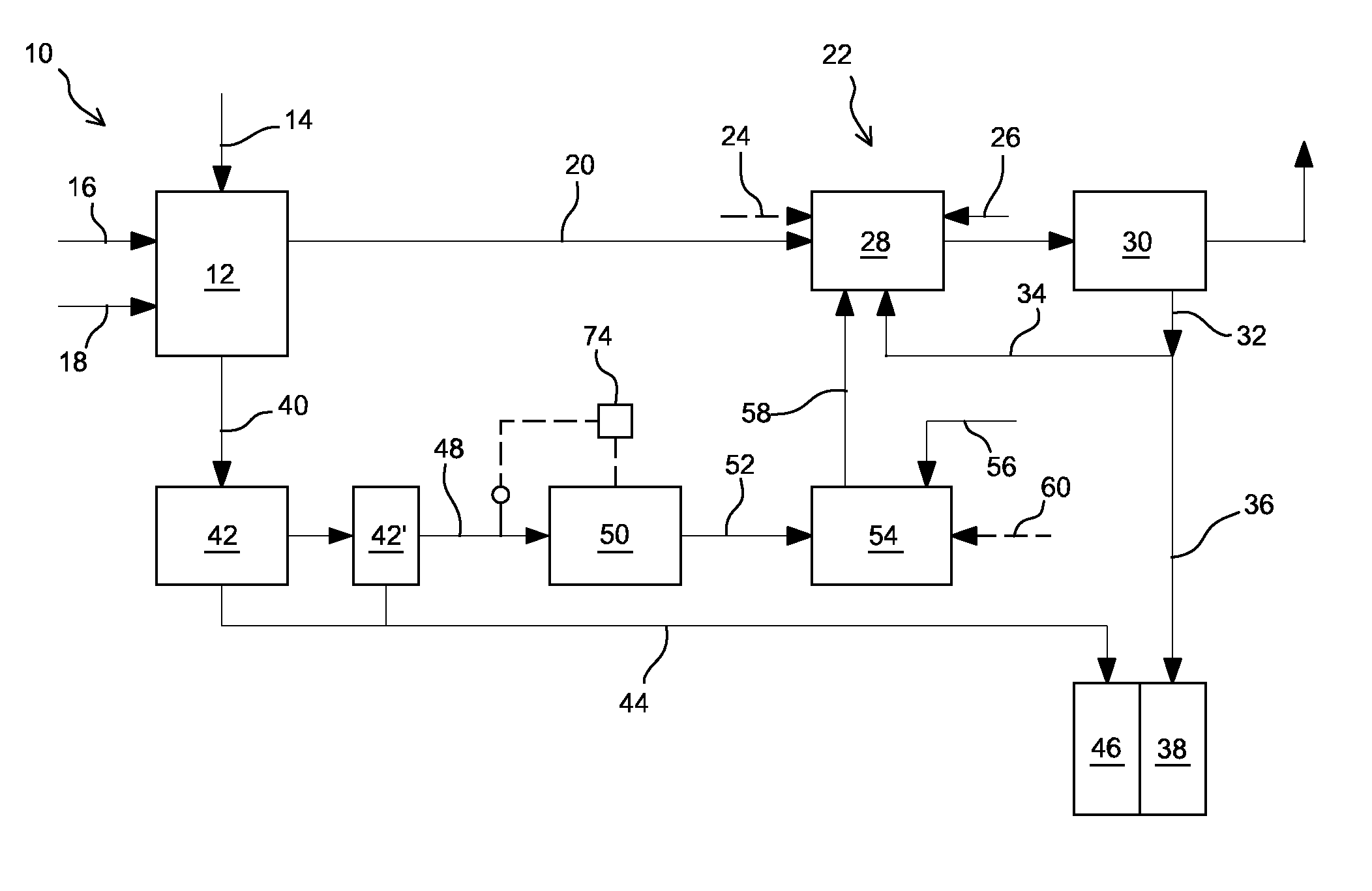
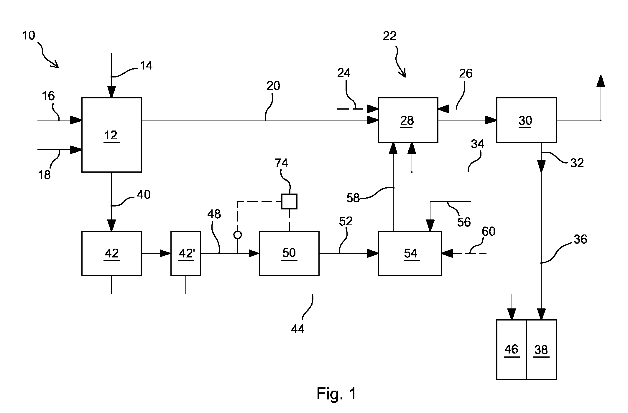
[0034]The schematic diagram of FIG. 1 shows a circulating fluidized bed (CFB) boiler (10) with a dry circulating fluidized bed (CFB) scrubber (22) for reducing sulfur oxide emissions from the boiler. The furnace (12) of the boiler comprises feeds for introducing sulfur-containing fuel (14), such as coal, petcoke or biofuel, CaCO3-containing sulfur sorbent (16), such as limestone, and inert bed material (18), such as sand, into the furnace. The fuel is combusted in the furnace with combustion gas, such as air (not shown in FIG. 1) to generate steam (not shown in FIG. 1). During the combustion, the sulfur in the fuel oxidizes to sulfur oxides, mainly SO2. In the temperatures prevailing in the furnace of a CFB boiler, typically, from 750° C. to 950° C., the CaCO3 in the sorbent is calcined to CaO, which combines with SO2 to CaSO3, which again oxidizes to CaSO4. Because the sulfation of the CaO particles takes place mainly on the outer surface of the particles, the utilization of the Ca...


PUM

PropertyMeasurementUnit
Contentaaaaaaaaaa

Abstract

Sulfurous fuel and CaCO3-containing sorbent are combusted in a furnace of a circulating fluidized bed boiler. A dry circulating fluidized bed scrubber includes a reactor with water and Ca(OH)2 feeds for converting SO2 in the exhaust gas to CaSO3 and CaSO4 and a dust separator in gas flow connection with the reactor. A discharge removes CaO-containing bottom ash from the furnace. A classifier classifies a portion of the removed CaO-containing bottom ash into coarse and finer portions. A fine ash channel conveys some of the finer bottom ash portion from the classifier to a grinder. A ground ash channel conveys some of the ground bottom ash portion from the grinder to a hydrator to hydrate CaO in the ash to Ca(OH)2. A hydrated ash channel conveys some of the Ca(OH)2 from the hydrator to the dry circulating fluidized bed scrubber as a sorbent.

Description

CLAIM OF PRIORITY[0001]This application is a U.S. national stage application of PCT International Application No. PCT / EP2012 / 074438, filed Nov. 22, 2013.BACKGROUND OF THE INVENTION[0002]Field of the Invention[0003]The present invention relates to a method of and an apparatus for combusting sulfurous fuel in a circulating fluidized bed boiler. The invention especially relates to reducing sulfur dioxide (SO2) content in the exhaust gas emanating from a circulating fluidized bed (CFB) boiler by using a dry circulating fluidized bed (CFB) scrubber.[0004]Description of the Related Art[0005]When combusting sulfur-containing fuels, the sulfur in the fuel is converted to sulfur oxides, mainly, sulfur dioxide, which may be harmful if emitted to the environment in large quantities. Dry flue gas scrubbing in a circulating fluidized bed scrubber is a commonly used method to reduce SO2 content in the flue gases emanating from different kinds of plants, such as power boilers, cement kilns, glass ...

Claims


Application Information

Patent Timeline
IPC IPC(8): B01D53/73F23C10/00B01D53/12B01D53/50F23J15/00F23J7/00F23J1/00
CPCB01D53/73B01D53/12B01D53/508F23C10/00F23C10/002F23J1/00F23J7/00F23J15/003B01D2251/404B01D2251/604B01D2251/606B01D2257/302B01D2258/0283F23J2215/20F23J2215/60F23J2900/01001F23J2900/01003
Inventor BRAND, TOBIASKUIVALAINEN, REIJOMOBS, MARIA-HELENAGRAF, ROLF
Owner AMEC FOSTER WHEELER ENERGIA
Why Eureka
Try Eureka