
Method for forming a micro-surface structure and for producing a micro-electromechanical component

a micro-surface structure and micro-electromechanical technology, applied in the field of methods, can solve the problems of gas activating other damaging mechanisms, harmful penetrating gases, and undesirable oxygen, hydrogen and water vapour in hermetic housings

Active Publication Date: 2017-05-02
FRAUNHOFER GESELLSCHAFT ZUR FOERDERUNG DER ANGEWANDTEN FORSCHUNG EV
View PDF26 Cites 5 Cited by
  • Summary
  • Abstract
  • Description
  • Claims
  • Application Information

AI Technical Summary

Benefits of technology

The present invention relates to a method for producing micro components or functional groups with improved mechanical integrity and stability, as well as increased effective surface area for the same or better function. The method involves applying a functional material to a substrate in a way that preserves its mechanical integrity and prevents flaking of the surface. The functional material is introduced in a second fine structure with solid members that protrude from the surface of the first fine structure, which leads to a dual structural enlargement of the functional material. The first fine structure provides a larger surface area for the substrate, allowing for more functional material to be applied. The method is simple and not complex, and can be carried out without interrupting the vacuum required for the application of the functional material. A gold covering layer can be vapor deposited without interrupting the vacuum, and can be selectively etched or thermally alloyed with the functional material or getter layer. The functional material can be structured, for example by using a layer of lacquer or a shadow mask.

Problems solved by technology

In numerous micro components, penetrating gases are harmful when the function of the component is based on controlled vacuum conditions or the maintenance of a specific pressure.
In particular, oxygen, hydrogen and water vapour are undesirable in hermetic housings.
In addition to the resultant pressure increase, however, gases can also activate other damaging mechanisms.
However, for reasons of mechanical component stability and component size, this geometric approach often can no longer be used or can be used only in a limited manner.
The trend towards increasingly small component geometries is counterproductive with respect to a sufficiently long function of the functional or getter material since there is, for example, no sufficiently planar surface for arrangement of the material, whereby a critical situation may occur with components which require a longer service-life.
The lateral arrangement often used in this instance disadvantageously increases the size of the component so that the quantity of the functional or getter material available in the housing is also limited.
The vertical arrangement saves space, but any particles which occur disadvantageously fall directly onto the sensitive component structure.
The integration of a getter material or other functional material into a vacuum wafer bonding process for producing micro components places high demands on the material itself.
Another problem which occurs when getters are used is described below.
Since the oxides and nitrides formed take up a larger volume than the converted getter material, the chemical reaction of the getter is also associated with the development of mechanical stress which under some circumstances can exceed a critical level and can bring about flaking or similar material defects in the getter structure.
Although the formation of the oxides and nitrides can also lead to the reactivity of the getter being limited, these layers hinder the further reaction of the getter with the gases.

Method used


Image

  • Method for forming a micro-surface structure and for producing a micro-electromechanical component
  • Method for forming a micro-surface structure and for producing a micro-electromechanical component
  • Method for forming a micro-surface structure and for producing a micro-electromechanical component

Examples


Embodiment Construction

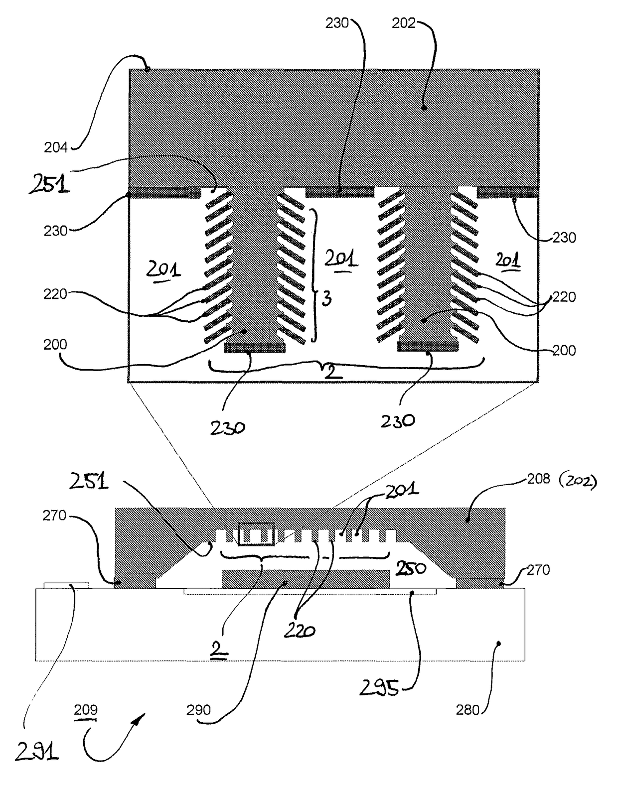
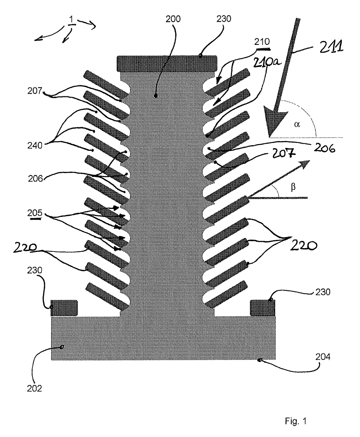
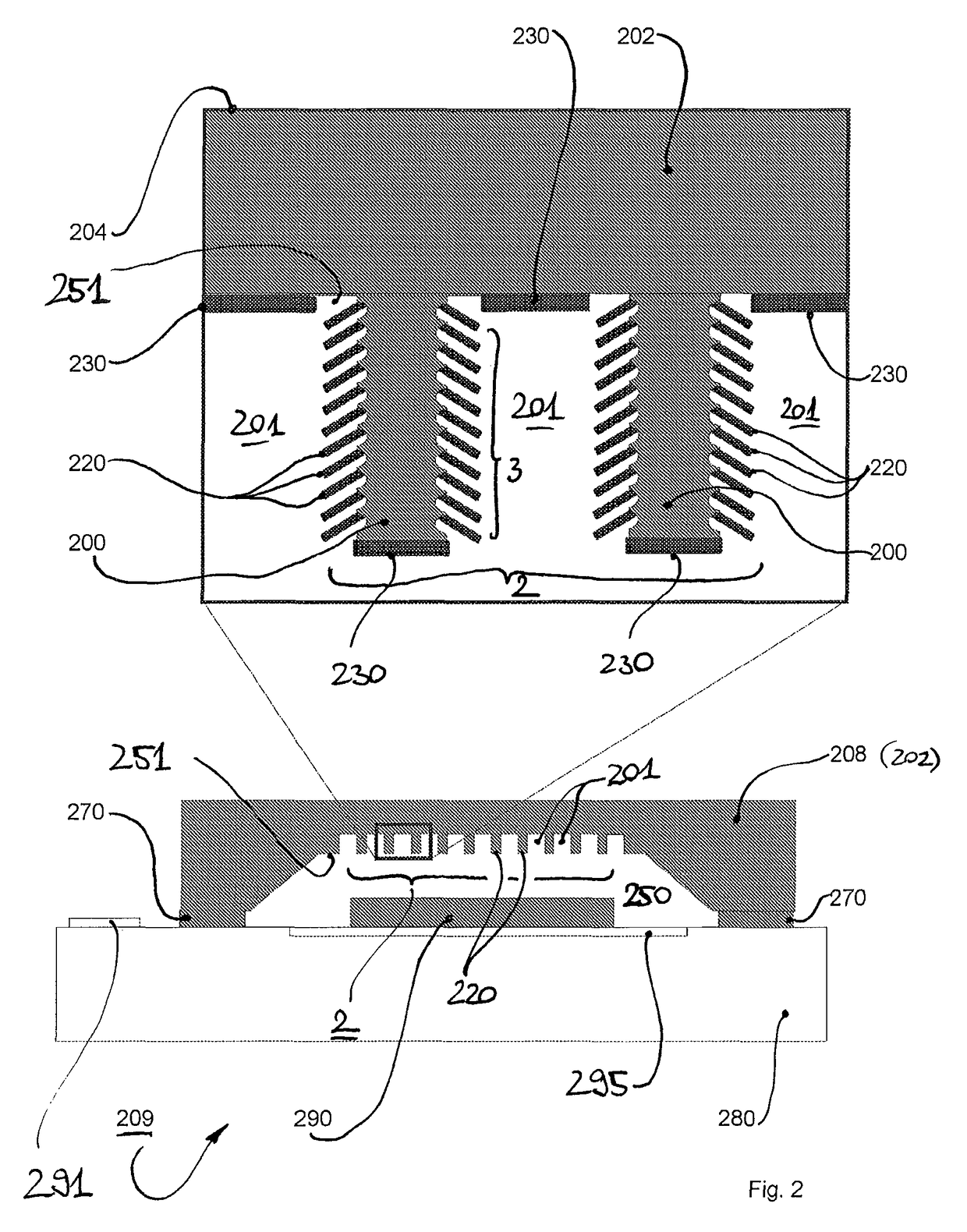
[0040]In FIG. 1, a portion of a micro-surface structure 1 according to the invention is greatly enlarged and illustrated schematically. The micro-surface structure 1 is formed on a substrate 202. The greatly enlarged FIG. 1 illustrates only one solid member 200 of the micro-surface structure 1. This member protrudes perpendicularly relative to the substrate plane 204. This plane extends in the direction of the arrow illustrated in FIG. 1 and perpendicularly relative to the plane of projection. As cannot clearly be seen from FIG. 1, the solid member 200 has a substantially circular cross-section in a cross-section parallel to the substrate plane 204. The surface 205 of the solid member 200 that extends perpendicularly relative to the substrate plane 204 is provided with a wave structure 210 which consists of wave troughs at 206 and wave peaks 207.

[0041]The functional material applied to the substrate surface is in the example illustrated a getter material 220, 230 comprising, for exa...


PUM

PropertyMeasurementUnit
heightaaaaaaaaaa
angleaaaaaaaaaa
angleaaaaaaaaaa

Abstract

The present invention relates to a method for forming a micro-surface structure on a substrate, in particular for producing a micro-electromechanical component, a micro-surface structure of this type, a method for producing a micro-electromechanical component having a micro-surface structure of this type and such a micro-electromechanical component. The invention is particularly relevant for components of microsystem technology (MST, micro-electromechanical systems MEMS) and the construction and connection technology for hermetically housing micro components, preferably using getter materials.

Description

FIELD OF THE INVENTION[0001]The present invention relates to a method for forming a micro-surface structure on a substrate, in particular for producing a micro-electromechanical component, a micro-surface structure of this type, a method for producing a micro-electromechanical component having a micro-surface structure of this type and such a micro-electromechanical component. The invention is particularly relevant for components of microsystem technology (MST, micro-electromechanical systems MEMS) and the construction and connection technology for hermetically housing micro components, preferably using getter materials.BACKGROUND OF THE INVENTION[0002]For reliable operation in a desired period of use of a micro component, for example a micro-electromechanical component such as a micro sensor or micro actuator, the atmosphere in the component is intended to be adjusted and maintained in accordance with the function. In numerous micro components, penetrating gases are harmful when th...

Claims


Application Information

Patent Timeline
Patent Type & Authority Patents(United States)
IPC IPC(8): B05D5/12B81C1/00H01L23/26G01J5/04B81B7/00B32B3/30
CPCB81C1/00206B81B7/0038G01J5/045H01L23/26Y10T428/24174B32B3/30H01L2924/0002Y10T29/4913Y10T428/24612H01L2924/00
Inventor REINERT, WOLFGANGQUENZER, JOCHENGRUBER, KAIWARNAT, STEPHAN
Owner FRAUNHOFER GESELLSCHAFT ZUR FOERDERUNG DER ANGEWANDTEN FORSCHUNG EV
Learn More