Fluorescent probes for monitoring voltage by photo-induced electron transfer

a technology of photoinduced electron transfer and fluorescent probes, which is applied in the direction of fluorescence/phosphorescence, instruments, apoptosis detection, etc., can solve the problems of water solubility and hinder the synthesis of water, and achieve the effect of reducing the operative parameters, reducing the efficiency of the pet between the fluorophore and the inducible quencher moiete, and reducing the synthesis

Active Publication Date: 2017-05-16
RGT UNIV OF CALIFORNIA
View PDF8 Cites 5 Cited by
  • Summary
  • Abstract
  • Description
  • Claims
  • Application Information

AI Technical Summary

Benefits of technology

[0008]Compounds and methods of the present invention employ a unique mechanism for voltage sensing, i.e. photo-induced electron transfer through molecular wires. The present invention circumvents art-recognized constraints set by the principle of exponential distance dependence of electron transfer to permit intramolecular, photo-inducible electron transfer (PeT) to occur at greater distances, thereby allowing voltage detection to take place across a larger fraction of a cellular membrane. The design of the compound, i.e. a molecular wire joining the fluorophore and inducible quencher moieties described herein, changes the mechanism of electron transfer from superexchange at close distances to electron hopping at larger distances. Efficiency of PeT between the fluorophore and inducible quencher moieties is altered in response to different voltage conditions, e.g. ranging from the potential at hyperpolarized state to depolarized state in the context of a cellular membrane. Quenching of the fluorescent moiety by the quencher moiety modulates the fluorescence quantum yield independent of wavelength, thereby permitting more efficient use of photons for excitation and emission, and lowering the operative parameters for light levels and dye concentrations.
[0009]Unlike conventional detection methods involving FRET dyes, compounds of the present invention place little to no capacitative load on the membrane and do not affect neuronal excitability. Other features exhibited by the compounds described herein include wavelength-independent sensitivity, fast response to changes in voltage in pace with biological fluctuations, slowed photobleaching, reduced phototoxicity, genetic targetability, and synthetic tractability for chemical modification. See Table 1 below outlining the various advantages of PeT-based dyes over electrochromic or FRET-based methods for voltage sensing. Since the quenching mechanism used by these compounds alters the ΦFl, decreases the brightness of the fluorophore, and does not shift the wavelength as do electrochromic methods, lower intensity light can be used, thereby reducing phototoxicity and permitting longer experimental duration. Those familiar with the art will know that electrochromic dyes require the entire voltage-sensing chromophores to be rigid in order to enable π orbital overlap, quantum yield, efficient charge transfer, and maximization of voltage sensitivity. Such rigidity in turn hinders synthesis and water solubility. The presently described PeT compounds are not subject to these constraints as the molecular wire need not be rigidly coplanar to function and synthesis of longer wires is feasible and sensitivity-enhancing, a phenomenon not observed with electrochromic dyes. Furthermore, the efficiency of PeT can be tuned via rational selection of the electron affinities of the donor, wire, and acceptor to maximize fluorescence turn-on in response to depolarizations.

Problems solved by technology

Such rigidity in turn hinders synthesis and water solubility.

Method used


Image

  • Fluorescent probes for monitoring voltage by photo-induced electron transfer
  • Fluorescent probes for monitoring voltage by photo-induced electron transfer
  • Fluorescent probes for monitoring voltage by photo-induced electron transfer

Examples


example 1

Design and Synthesis of VF Sensors

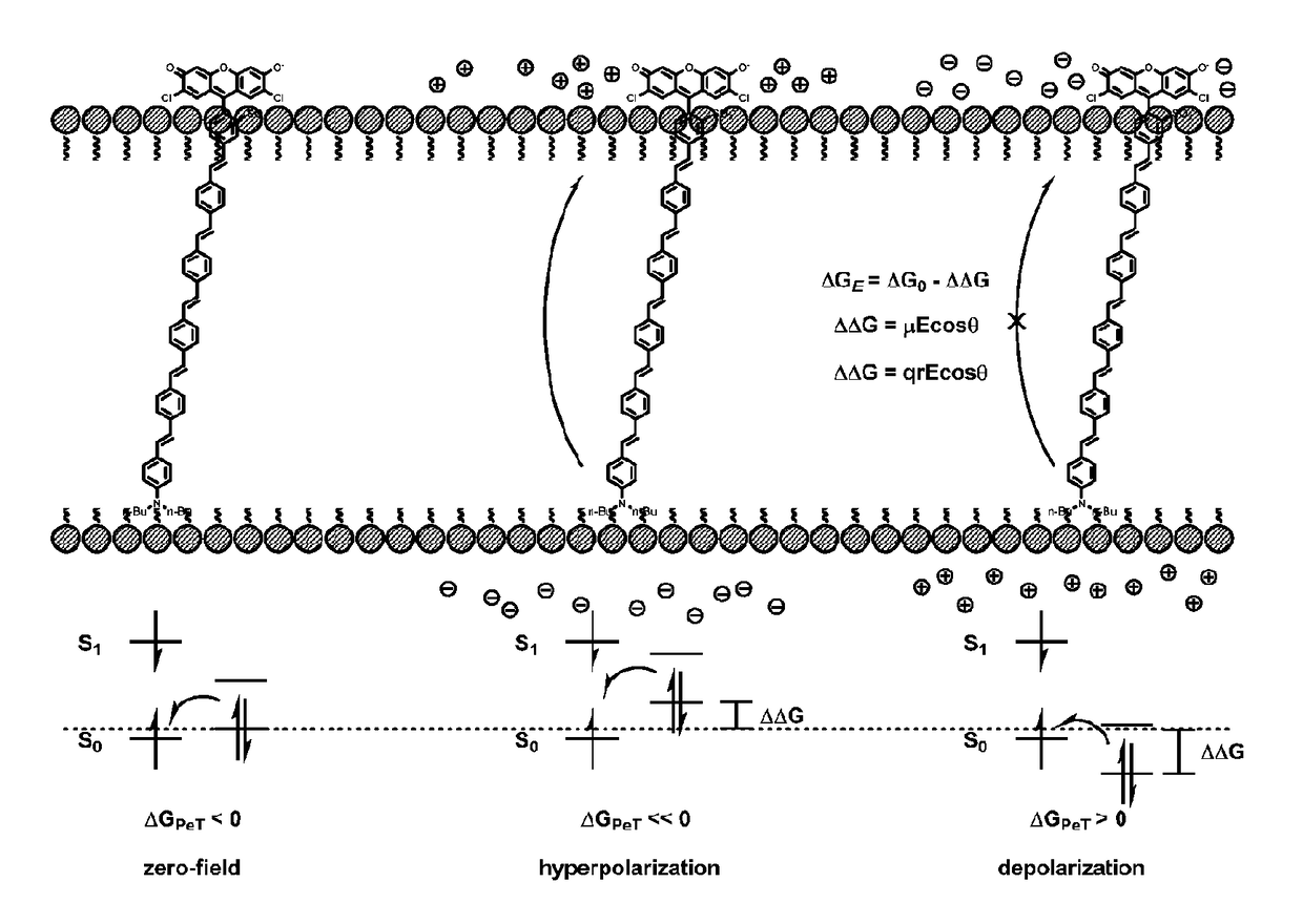
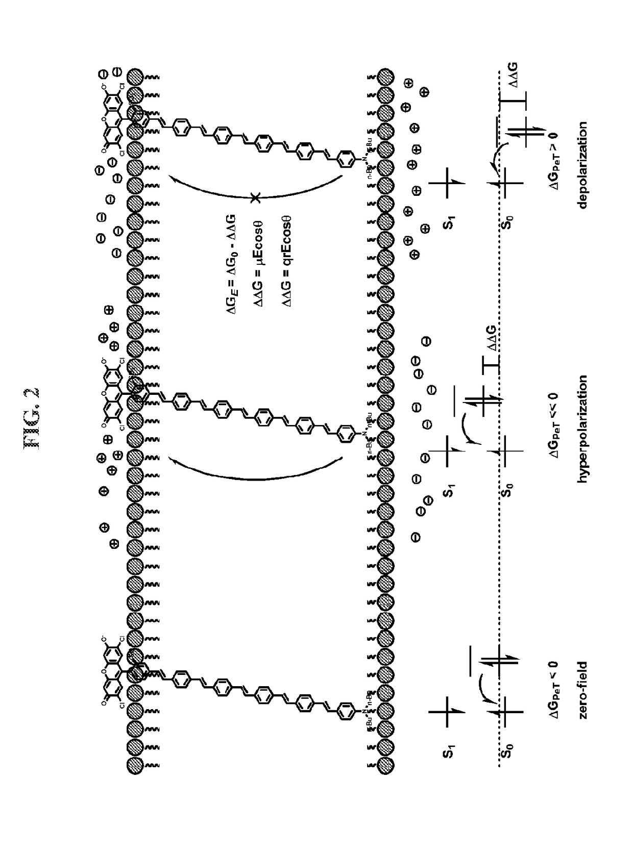
[0279]Our initial voltage sensors incorporate dichlorosulfofluorescein as a membrane-impermeant fluorophore, a p-phenylenevinylene (PPV) molecular wire, and N,N-dimethyl- or dibutylaniline as an electron-rich quencher (Scheme 1). VF1.4.Cl comprises 2,7-dichlorosulfofluorescein connected via one vinylene unit to dibutylaniline (hence VF1.4.Cl). VF2.4.Cl adds a second PPV unit, and VF2.1.Cl features the same configuration, with methyl substituted in place of butyl groups.

[0280]

[0281]Correct positioning of the fluorophore-wire donor within the membrane is vital to take advantage of the vectoral nature of the transmembrane electric field and electron transfer. First, the longitudinal axis of the molecular wire must be normal to the plane of the plasma membrane, to sample the full electric field. Second, dye molecules must all align in the same direction to avoid canceling out the electron transfer effect. Positioning the fluorophore at the extracellular...

example 2

Testing of VF1.4.Cl and VF2.4.Cl in HEK Cells

[0317]To test the efficacy of VF1.4.Cl and VF2.4.Cl as voltage sensors, the probes were loaded in HEK cells at a concentration of 2 μM. Passive staining for 15 minutes at 37° C. resulted in excellent membrane localization, as established by epifluorescence and confocal microscopy (FIG. 4). In contrast, when di-4-ANEPPS is loaded under identical conditions, significant internalization of the dye is observed. Optimal loading conditions for di-4-ANEPPS require loading for only 10 minutes at 4° C.

[0318]Membrane voltage of cells loaded with VF1.4.Cl or VF2.4.Cl were controlled by making tight-seal whole-cell recordings. Cells were maintained at a holding potential of −60 mV and stepped for 50 ms to various depolarizing and hyperpolarizing potentials (FIG. 5A), while simultaneously acquiring epifluorescence images. For both sensors, depolarizing steps result in fluorescence increases while hyperpolarizing steps decrease fluorescence intensity, ...

example 3

Characterization of VF Sensors in HEK Cells

[0321]The dibutyl (VFx.4.Cl) dyes stain the cell membranes of HEK293 cells when loaded at a concentration of 2 μM for 15 min at 37° C. in buffer with 0.1% DMSO as cosolvent (FIG. 9A, and FIG. 10). VF2.1.Cl requires even lower dye concentrations (100 nM) and gives bright staining of HEK cell membranes, which is likely to be because of the greater aqueous solubility of VF2.1.Cl compared with VF2.4.Cl in aqueous solution (FIG. 10). The membrane retention of the second generation dyes (VF2.x.Cl) is in contrast to di-4-ANEPPS, which at the same loading conditions, shows significant uptake into internal membranes. The bleach rates of the probes were tested in HEK cells and compared with di-4-ANEPPS. The bleach rates for VF1.4.Cl, VF2.4.Cl, and VF2.1.Cl at 7 W / cm2 were measured to be 3.9±0.1×10⁻² 1.8±0.1×10⁻² s−1, and 8.0±0.1×10⁻³ s−1, respectively. These results are two-, four-, and ninefold smaller than di-4-ANEPPS, which has a bleach rate, unde...


PUM

PropertyMeasurementUnit
pHaaaaaaaaaa
membrane potentialaaaaaaaaaa
frequencyaaaaaaaaaa

Abstract

Compounds and methods for determining transmembrane potential, monitoring changes in transmembrane potential, and / or drug screening are provided. In one aspect, compounds of the invention have a structure according to the formula: E-M-A, wherein A is a fluorophore, selected from xanthenes, coumarins, cyanines, bimanes, and difluoroboradizaindacenes, charged at physiological pH; M is a molecular wire; and E is a hydrophobic moiety, wherein A and E are capable of being involved in a photo-induced, intramolecular electron transfer that quenches the fluorescence of A in response to a voltage condition. When in use, compounds of the invention are membrane-impermeant and oriented within the cell membrane such that the charged moiety localizes at the outer leaflet of the lipid bilayer and the hydrophobic moiety and molecular wire associate with the hydrophobic portion of the lipid bilayer. The rate of electron transfer, fluorescence intensity, and quenching are altered in response to changes in transmembrane potential.

Description

CROSS REFERENCES TO APPLICATIONS[0001]This application is a 371 of International Patent Application No. PCT / US2012 / 038876, filed May 21, 2012, which claims priority to U.S. Provisional Patent Application Ser. No. 61 / 488,075, filed May 19, 2011, the disclosures of which are hereby incorporated herein by reference in its entireties for all purposes.STATEMENT OF GOVERNMENT SUPPORT[0002]This invention was made with government support under grants NS027177 and EB012423 awarded by NIH. The government has certain rights in the invention.BACKGROUND OF THE INVENTION[0003]Fluorescence imaging can map the electrical activity and communication of multiple spatially resolved neurons and thus complement traditional electrophysiological measurements (1, 2). Ca2+ imaging is the most popular of such techniques, because the indicators are well-developed (3-6), highly sensitive (5, 6), and genetically encodable (7-13), enabling investigation of the spatial distribution of Ca2+ dynamics in structures a...

Claims


Application Information

Patent Timeline
Patent Type & Authority Patents(United States)
IPC IPC(8): G01N21/64G01N33/50G01N33/542C09K11/06
CPCG01N21/6486C09K11/06G01N33/5008G01N33/542C09K2211/1007C09K2211/1011C09K2211/1088G01N2500/10
Inventor MILLER, EVAN WALKERTSIEN, ROGER Y.
Owner RGT UNIV OF CALIFORNIA
Why Eureka
Try Eureka