Reducing resonant effects of reactive loads in electric motor systems

a reactive load and electric motor technology, applied in the field of motor drives, can solve the problems of increasing the electromagnetic emissions of the system, generating significant electromagnetic interference (emi) from the drive motor, and high frequency damped sinusoidal ringing on the output pulse edges of the driver's square wave bridge, so as to reduce the resonant effects of reactive loads

Active Publication Date: 2017-12-05
HAMILTON SUNDSTRAND CORP
View PDF27 Cites 17 Cited by
  • Summary
  • Abstract
  • Description
  • Claims
  • Application Information

AI Technical Summary

Benefits of technology

[0013]According to another embodiment described herein is an electric motor control system with reduced resonant effects of reactive loads. The electric motor control system including a rectifier bridge, the rectifier bridge operably connected to a power source and a DC link, the rectifier bridge configured to supply the DC link, the DC link having a positive terminal and a ground terminal, an inverter operably connected to the DC link, the inverter converting a DC signal received from the DC link into a plurality of motor excitation signals, and an interface cable, the interface cable operably connected to the inverter, and configured to transmit the plurality of motor excitation signals. The electric motor control system also including a motor remote from and operably connected to the inverter via the interface cable, the motor responsive to the plurality of motor excitation signals; and a plurality of snubber circuits, each of the snubber circuits of the plurality of snubber circuits having a first terminal operably connected to a different winding of the motor, and a second terminal operably connected to a first end of a transmission line, wherein a second end of the transmission line is operably connected to the positive terminal of the DC link.
[0014]Also described herein in yet another embodiment is a method of reducing the resonant effects of reactive loads in electric motor systems with a DC link having a positive terminal and a ground terminal and an inverter operably connected to the DC link. The method includes generating a plurality of motor excitation signals with the inverter, carrying the motor excitation signals from the inverter with an interface cable to a motor remote from the inverter, the motor responsive to the plurality of motor excitation signals, and reducing a Q factor of an interface between the inverter and the motor at an oscillation frequency associated with the plurality of excitation signals with a plurality of snubber circuits, each of the snubber circuits of the plurality of snubber circuits having a first terminal operably connected to a different winding of the motor, and a second terminal operably connected to a first end of a transmission line, wherein a second end of the transmission line is operably connected to the positive terminal of the DC link.

Problems solved by technology

However, timing and switching of power in an inverter to drive a motor generates significant electromagnetic interference (EMI).
This cable, in conjunction with the reactance of the motor and parasitic winding capacitance, creates high Q factor common mode resonances that result in high frequency damped sinusoidal ringing on the square wave bridge driver output pulse edges.
This high frequency ringing increases electromagnetic emissions from the system and interferes with the ability to monitor and control the motor phase currents.
The snubbers could be grounded to the motor case, but this could increase radiated electromagnetic emission levels due to increased structure currents.
CM noises can be problematic for motor drives because CM noises increase the EMI in the motor drive and can damage the motor bearing and winding insulation.
Unfortunately, in certain applications, solutions such as adding CM filters to attenuate CM noises are not viable due to the significant weight penalty of each CM filter.

Method used


Image

  • Reducing resonant effects of reactive loads in electric motor systems
  • Reducing resonant effects of reactive loads in electric motor systems
  • Reducing resonant effects of reactive loads in electric motor systems

Examples


Embodiment Construction

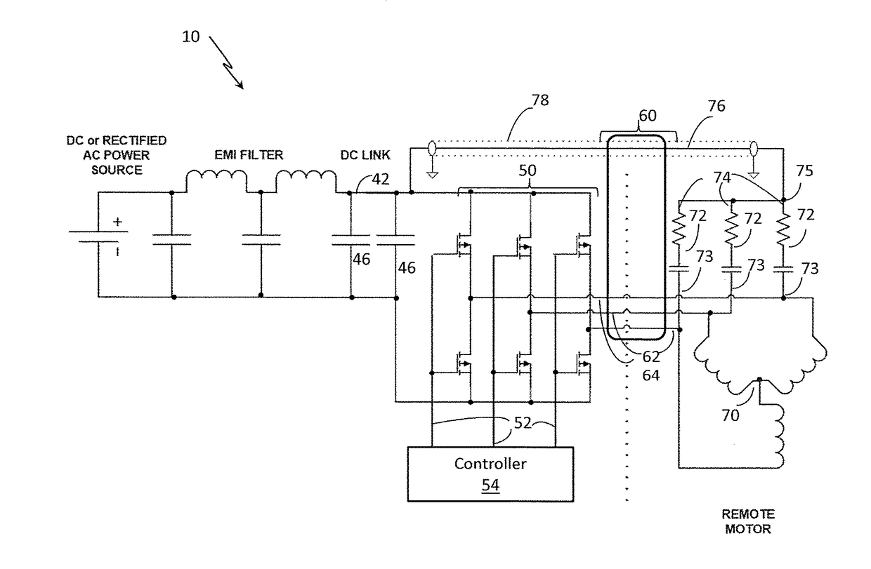
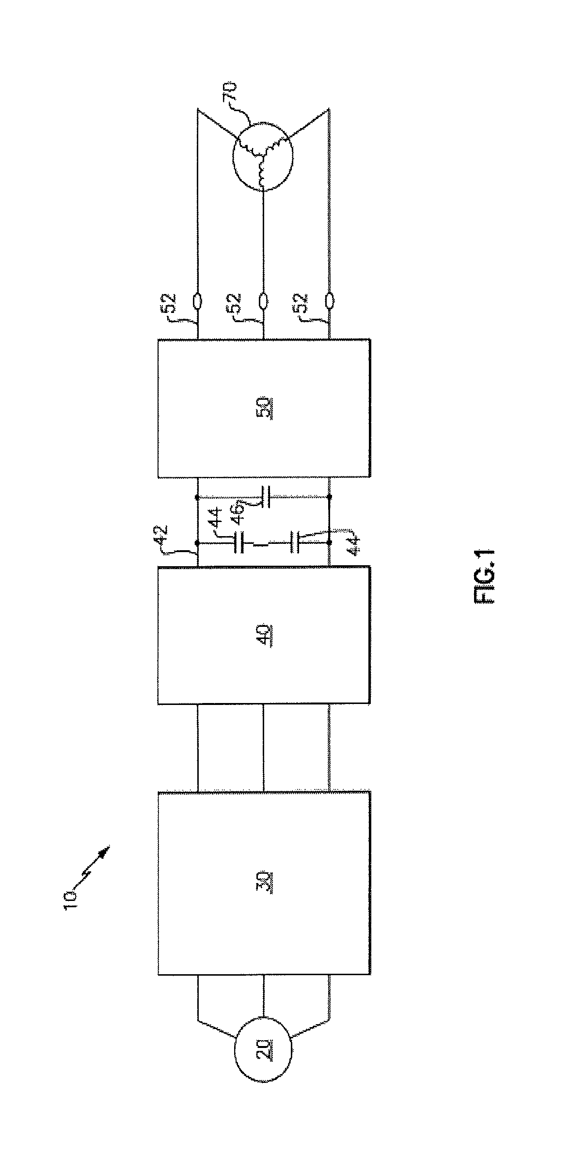
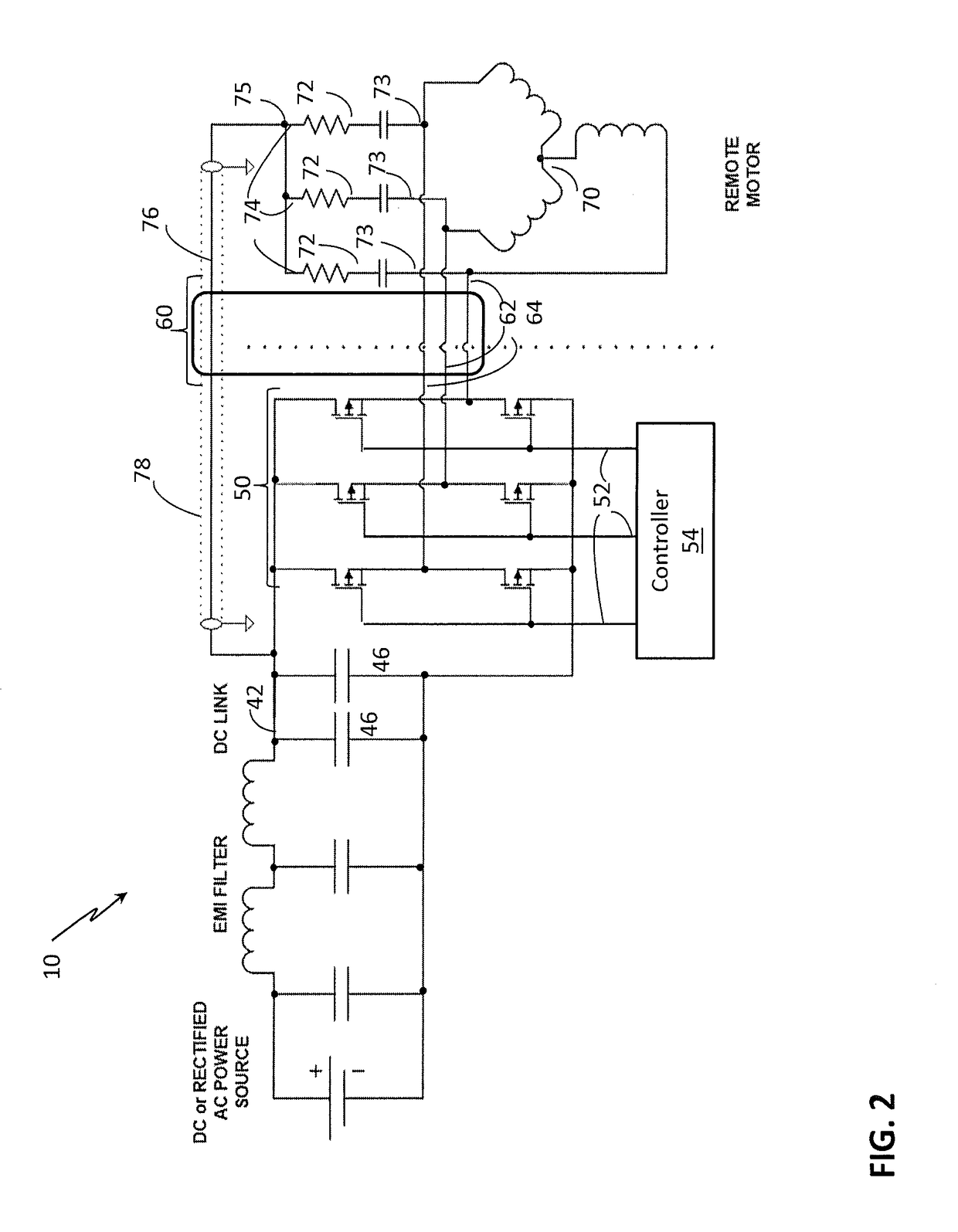
[0027]Generally, the switching of power electronics devices in actively controlled inverters also generates electromagnetic interference (EMI). EMI filters are designed to attenuate EMI noise to satisfy the EMI standards, which are defined for particular applications, but EMI filters add weight and complexity for the motor drive system. Thus, alternative means to reduce EMI are commonly considered. In general, embodiments herein relate to a motor drive that receives DC power from a DC bus supplied by an active or passive rectifier bridge. The motor drive is located remotely from the motor and significant EMI can result. A snubber network and transmission line is employed to address the EMI concerns. In particular, the embodiments herein relate a snubber network and its connection between a motor and the DC bus. Embodiments herein set forth a drive and motor system and / or method for control of motor system driven by a motor drive or inverter to control EMI. In an embodiment, three sn...


PUM


Abstract

Embodiments herein relate to a drive system for an electric motor. The drive system including a DC bus having a positive terminal and a ground terminal, an inverter connected to the DC bus configured to provide a plurality of motor excitation signals, and an interface cable operably connected to the inverter, and configured to transmit the plurality of motor excitation signals. The drive system also includes a motor remote from and connected to the inverter via the interface cable, the motor responsive to the motor excitation signals and a plurality of snubber circuits, each of the snubber circuits having a first terminal connected to a winding of the motor, and a second terminal operably connected to a first end of a transmission line and a second end of the transmission line is connected to the positive terminal of the DC Bus.

Description

TECHNICAL FIELD[0001]The subject matter disclosed herein relates generally to the field of motor drives, and more particularly to a motor drive electrical filters to reduce electromagnetic interference (EMI).BACKGROUND[0002]The typical brushless DC or three phase electric motor driven by a three phase bridge or inverter uses the motor windings to integrate the square wave output drive pulses from the bridge. However, timing and switching of power in an inverter to drive a motor generates significant electromagnetic interference (EMI). When the controller, and thereby the bridge or inverter driver circuit is remotely located from the motor load, a three conductor shielded cable is commonly employed as the interface between the driver and motor. This cable, in conjunction with the reactance of the motor and parasitic winding capacitance, creates high Q factor common mode resonances that result in high frequency damped sinusoidal ringing on the square wave bridge driver output pulse ed...

Claims


Application Information

Patent Timeline
Patent Type & Authority Patents(United States)
IPC IPC(8): H02P1/00H02H7/09H02P29/50H02P6/14H02P27/08
CPCH02P29/50H02P6/14H02P27/08H02M1/126
Inventor CARCIA, FRANCIS A.JONKE, CHRISTOPHER J.
Owner HAMILTON SUNDSTRAND CORP
Why Eureka
Try Eureka