Composite friction elements and pultrusion method of making same

a technology of friction elements and friction elements, which is applied in the direction of friction elements, friction linings, other domestic articles, etc., can solve the problems of releasing potentially harmful amounts of it into the environment, affecting the quality of friction units made by this method, and consuming a lot of resources

Active Publication Date: 2018-02-06
BOOHER BENJAMIN V
View PDF15 Cites 3 Cited by
  • Summary
  • Abstract
  • Description
  • Claims
  • Application Information

AI Technical Summary

Benefits of technology

[0012]According to one aspect, a system for continuous process manufacturing of composite friction units comprises one or more array gates, a resin plenum, and a forming die. The one or more array gates comprise a plurality of cutouts, each of the plurality of cutouts sized to receive one reinforcing fiber fabric of a plurality of reinforcing fiber fabrics therethrough. The resin plenum comprises a plenum chamber within a body and a plurality of dispensing tube assemblies in fluid communication with the plenum chamber, each of the plurality of dispensing t

Problems solved by technology

Unfortunately, pressure is not the only factor that influences the frictional response of the brake elements.
The materials forming the composition element are the principle unpredictable variables that have the greatest affect on the performance characteristics of the brake system.
However, it was discovered that asbestos is a carcinogenic substance, and that such use released potentially harmful amounts of it into the environment.
These efforts have been frustrated by the many and varied parameters involved, including the range of needs to be met between brakes and

Method used


Image

  • Composite friction elements and pultrusion method of making same
  • Composite friction elements and pultrusion method of making same
  • Composite friction elements and pultrusion method of making same

Examples


example 1

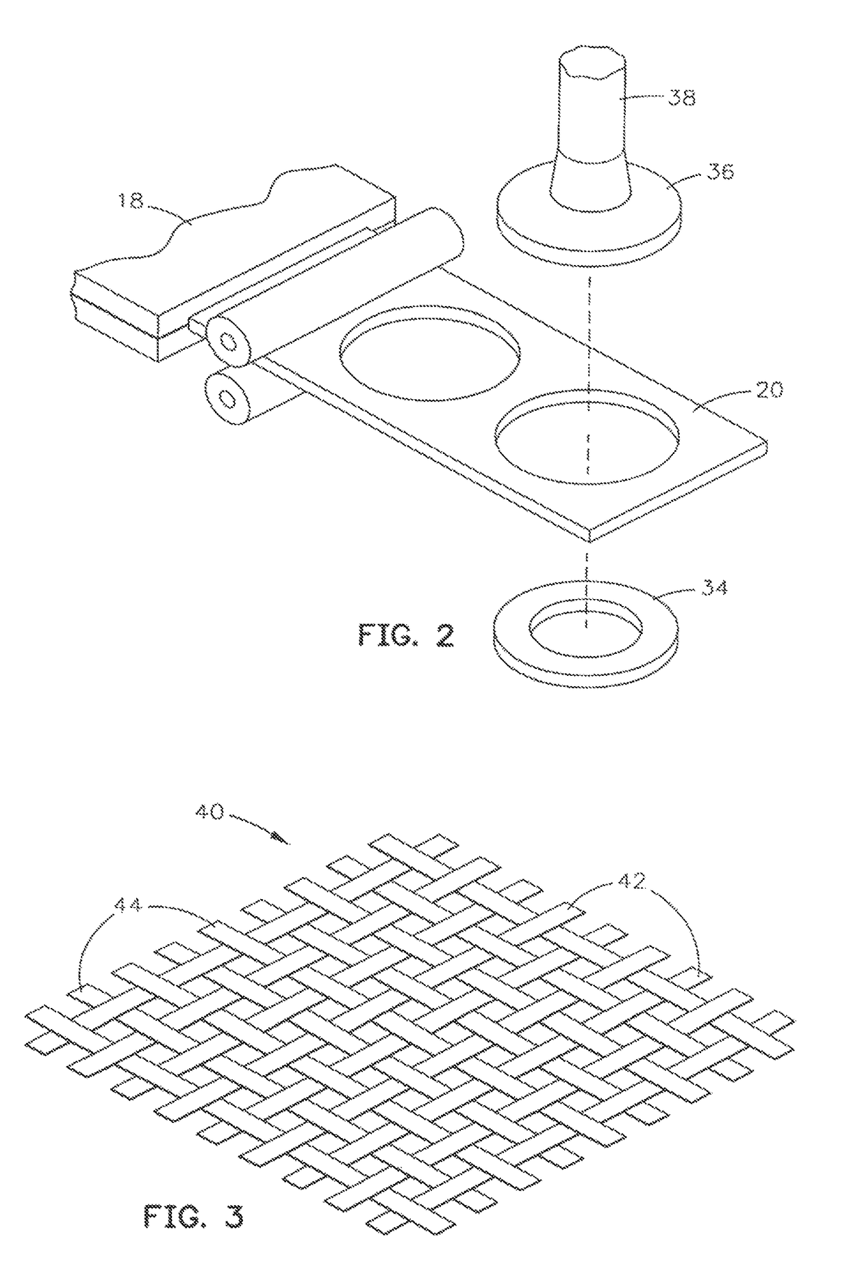
[0081]A suitable test sample of the product was produced having the composition of a wetting agent of about 0.035%, Barytes (BaS04) of about 5.5%, Copper of about 6.9%, walnut flour of about 2.8%, Talc Nytal (CaMgSilicatelH20) of about 2.8%, graphite of about 3.5%, Zinc Oxide (friction enhancer) of about 4.1%, Aluminum Oxide (friction enhancer) of about 4.1% and Axel 1850 (mold release) of about 0.7%. The final product had about 46.0 wt % glass, about 30.30 wt % filler and about 33.7 wt % resin. The glass was PPG E type phenolic sized woven fabric.

example 2

[0082]

Raw MaterialWeight PercentPhenolic Resin12.66Barium Sulfate15.19Potassium Titanate12.66Kevlar2.53Calcium Fluoride5.06Antimony Trisulfid2.53Zircon2.53Aluminum Oxide1.27Syn Graphite7.59Coke 92.53Cashew Particles7.59Rubber5.06Calcium Oxide1.27Ceramic Fiber3.80Vermiculite10.13Copper7.59

example 3

[0083]

Raw MaterialWeight PercentPhenolic Resin10.53Barium Sulfate18.42Steel Wool 20521.05Kevlar0.00Calcium Fluoride 5.26Zinc Sulfide2.63Zircon3.95Aluminum Oxide1.32Syn Graphite7.89Coke 92.63Cashew Particles2.63Rubber5.26Calcium Oxide1.32Ceramic Fiber3.95Vermiculite10.53Copper2.63


PUM


Abstract

A system for continuous process manufacturing of composite friction units uses one or more array gates with a plurality of cutouts each sized to receive one of a plurality of reinforcing fiber fabric therethrough. The system also uses a resin plenum with plenum chamber and a plurality of dispensing tube assemblies. Each of the plurality of dispensing tube assemblies corresponds to a different cutout and includes dispensing bores positioned to dispense resin onto one of the reinforcing fiber fabrics. The system also uses a forming die that receives the reinforcing fiber fabrics with the resin to form a composite panel as they pass through the forming die.

Description

CROSS REFERENCE TO RELATED APPLICATIONS[0001]This Application is a continuation-in-part of earlier U.S. patent application Ser. No. 13 / 796,212, filed Mar. 12, 2013, now issued as U.S. Pat. No. 8,974,621 on Mar. 10, 2015, which is a divisional application of earlier U.S. patent application Ser. No. 12 / 841,657, filed Jul. 22, 2010, now issued as U.S. Pat. No. 8,394,226 on Mar. 12, 2013, which is a continuation-in-part of earlier U.S. patent application Ser. No. 10 / 164,191, filed Jun. 5, 2002, now abandoned, the disclosures of which are hereby incorporated herein by reference.BACKGROUND OF THE INVENTION[0002]The present invention relates to composite friction elements for brakes and clutches and pertains particularly to improved friction elements, composition and method for making same.[0003]A friction brake is basically a pair of friction members, one rotating and one stationary, brought into engagement to produce a friction force measured as brake torque for either slowing or stoppin...

Claims


Application Information

Patent Timeline
IPC IPC(8): B29C70/02B05C5/02B29L31/16
CPCB29C70/025B29L2031/16B05C5/025B05C5/0245B05C5/0233B05C5/0275B05C5/027B29K2995/0087B29C70/525B29C70/545B32B5/08B32B15/14B32B17/02B29C70/24F16D69/026F16D2200/0065B29K2061/04Y10T156/1062Y10T156/1085B32B5/02B32B5/26B32B2260/023B32B2260/046B32B2475/00
Inventor BOOHER, BENJAMIN V.
Owner BOOHER BENJAMIN V
Why Eureka
Try Eureka