
Electrochemical light emitting cell, composition for forming light emitting layer of electrochemical light emitting cell, and ionic compound for light emitting layer of electrochemical light emitting cell

a light-emitting cell and electrochemical technology, applied in the field of electrochemical light-emitting cells, can solve the problems of many manufacturing steps, many restrictions in selecting the electrode materials for forming positive and negative electrodes, and the limitation of the electrode materials is not so great, so as to improve the properties of the organic thin film forming the emitting layer, increase the rate of re-arrangement of ions, and improve the effect of the compatibility between the organic ionic compound

Active Publication Date: 2018-04-03
NIPPON CHECMICAL IND CO LTD +1
View PDF12 Cites 4 Cited by
  • Summary
  • Abstract
  • Description
  • Claims
  • Application Information

AI Technical Summary

Benefits of technology

The aim of studying an organic ionic compound is to improve the properties of the organic thin film that forms the emitting layer, by increasing its compatibility with the light-emitting substance and facilitating the movement of ions and electrons. By selecting the appropriate cation and anion species composing the ionic compound, there is a need for an ionic compound that is compatible with many kinds of light-emitting substances.

Problems solved by technology

Consequently, an organic EL device has a complicate multi-layer structure and involves many manufacturing steps.
Moreover, there are many restrictions in selecting the electrode materials forming positive and negative electrodes because the work function should be taken into consideration.
Furthermore, in the manufacture of LECs, because consideration of the work function is not required in selecting the electrode materials, limitation to the electrode materials is not so great.

Method used


Image

  • Electrochemical light emitting cell, composition for forming light emitting layer of electrochemical light emitting cell, and ionic compound for light emitting layer of electrochemical light emitting cell
  • Electrochemical light emitting cell, composition for forming light emitting layer of electrochemical light emitting cell, and ionic compound for light emitting layer of electrochemical light emitting cell
  • Electrochemical light emitting cell, composition for forming light emitting layer of electrochemical light emitting cell, and ionic compound for light emitting layer of electrochemical light emitting cell

Examples


examples

[0065]The invention will now be illustrated in greater detail with reference to Examples, but it should be understood that the invention is not deemed to be limited thereto. The characteristics were determined in Examples and Comparative Examples by the following methods.

Determination of Luminance:

(1) In Examples 1 to 20 and Comparative Examples 1 to 10

[0066]The first electrode of the LEC obtained was connected to the positive terminal of a direct current, and the second electrode to the negative terminal. A voltage was applied at a sweep rate of 1 V / sec up to 15 V. The maximum luminance reached during the voltage application was taken as the luminance of the LEC. Measurements were made using a luminance meter CS-2000 from Konica Minolta.

(2) In Examples 21 to 24

[0067]The tint electrode of the LEC obtained was connected to the positive terminal of a direct current, and the second electrode to the negative terminal. A voltage was applied at a sweep rate of 1 V / sec up to 6 V. The lumin...

examples 1 to 15

[0068]Examples in which a phosphonium cation was used as a cations of the ionic compound are presented.

[0069]A commercially available glass substrate coated with an ITO film (ITO film thickness: 200 nm; available from Geomatec) was used as a first electrode 13.

[0070]A mixed solution was prepared using the organic light emitting polymer shown in Table 1 as a light emitting material and the compound shown in Table 1 as an ionic compound. Specifically, an organic light-emitting polymer solution in toluene (conc.: 9 g / l) and an ionic compound solution in toluene (conc.: 9 g / l) were mixed at a volume ratio of 4:1 (the former:the latter) in a glove box filled with argon at mom temperature to prepare an emitting layer-forming composition.

[0071]The emitting layer-forming composition prepared above was applied to the first electrode 13 of the glass substrate by spin coating at room temperature in the glove box filled with argon and dried on a hot plate at 50° C. for 30 minutes to remove the ...

examples 16 to 20

[0072]Examples in which an ammonium cation was used as a cation of the ionic compound are presented.

[0073]A mixed solution was prepared using the organic light-emitting polymer shown in Table 1 as a light-emitting material and the compound shown in Table 1 as an ionic compound. Specifically, an organic light-emitting polymer solution in toluene (conc.: 9 g / l) and an ionic compound solution in toluene (conc.: 9 g / l) were mixed at a volume ratio of 4:1 (the former:the latter) in a glove box tilled with argon at room temperature to prepare an emitting layer-forming composition. An LEC 10 was made in otherwise the same manner as in Example 1. The results of the determination of the emission characteristics of the resulting LEC 10 are shown in Table 1.


PUM

PropertyMeasurementUnit
thicknessaaaaaaaaaa
thicknessaaaaaaaaaa
thicknessaaaaaaaaaa

Abstract

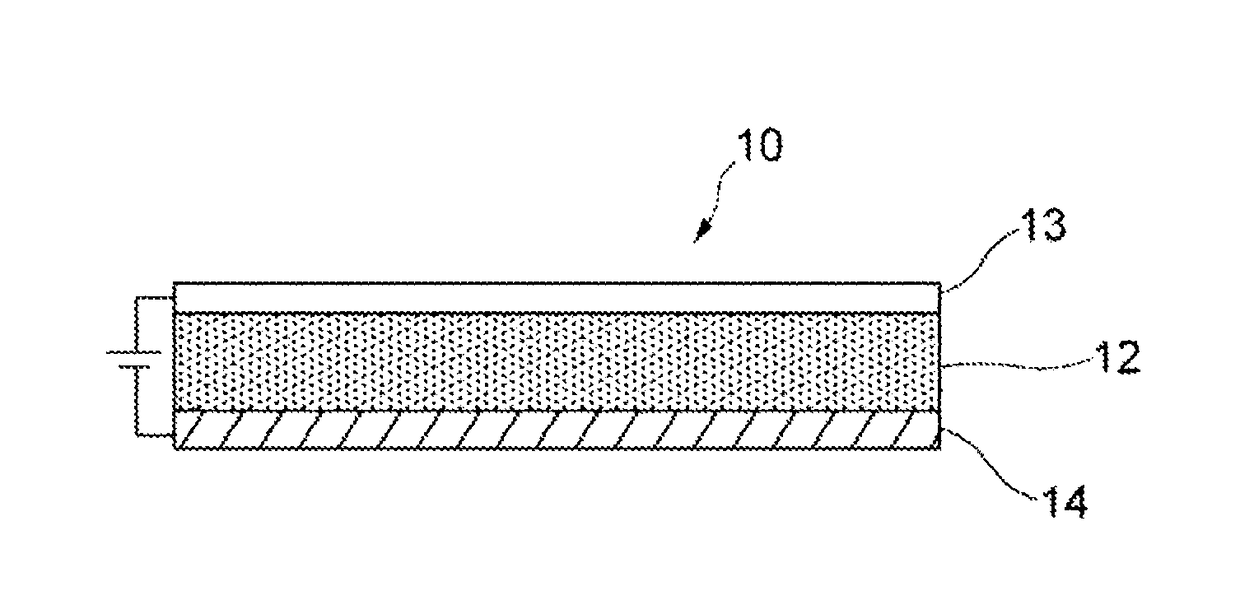
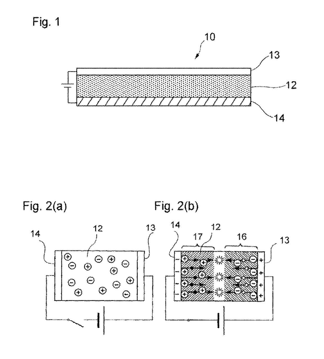
A light-emitting electrochemical cell 10 includes an emitting layer 12 and electrodes 13 and 14, one on each side of the emitting layer 12. The emitting layer 12 contains a light-emitting material and an ionic compound. The ionic compound has general formula (1), wherein M is N or P; R1, R2, R3, and R4 each independently represent a C1-C20 saturated aliphatic group; and X is preferably an anion having a phosphoric ester bond or a sulfuric ester bond. The light-emitting material is preferably an organic light-emitting polymer, a metal complex, an organic low molecular compound, or a quantum dot.

Description

TECHNICAL FIELD[0001]The invention relates to a light-emitting electrochemical cell having an emitting layer containing a light-emitting material and an ionic compound. The invention also relates to a composition for forming an emitting layer of a light-emitting electrochemical cell.BACKGROUND ART[0002]In recent years, development of organic electro luminescent (organic EL) devices, which emit light by themselves using electrons and positive holes as carriers, has been progressing rapidly. Organic EL devices are characteristically superior to liquid crystal devices, which do not emit light by themselves and therefore need a backlight, in terms of possibility of thickness and weight reduction, visibility, and the like.[0003]An organic EL device generally includes a pair of facing substrates having an electrode on their facing sides and an emitting layer interposed between the substrates. The emitting layer is formed of an organic thin film containing a light-emitting substance that e...

Claims


Application Information

Patent Timeline
Patent Type & Authority Patents(United States)
IPC IPC(8): H01L51/00H01L51/50H10K99/00
CPCH01L51/0039H01L51/004H01L51/005H01L51/0087H01L51/0065H01L51/5032H01L51/502F21K2/08C09K11/025C09K11/06C09K2211/14H10K85/115H10K85/654H10K50/135C09K2211/18H10K85/113H10K85/114H10K85/60H10K85/141H10K85/346H10K85/653H10K50/115
Inventor YONEKAWA, FUMIHIROSAKANOUE, TOMOTAKENOBU, TAISHI
Owner NIPPON CHECMICAL IND CO LTD
Learn More