Lubricant-impregnated surfaces for electrochemical applications, and devices and systems using same

a technology of electrochemical applications and impregnated surfaces, applied in the field of lubricant impregnated surfaces, can solve the problems of significant pumping energy loss, and/or decrease in electrochemical energy efficiency, and achieve the effect of reducing viscous drag

Active Publication Date: 2018-04-17
MASSACHUSETTS INST OF TECH
View PDF160 Cites 6 Cited by
  • Summary
  • Abstract
  • Description
  • Claims
  • Application Information

AI Technical Summary

Benefits of technology

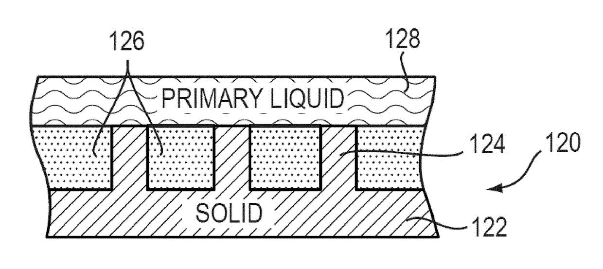
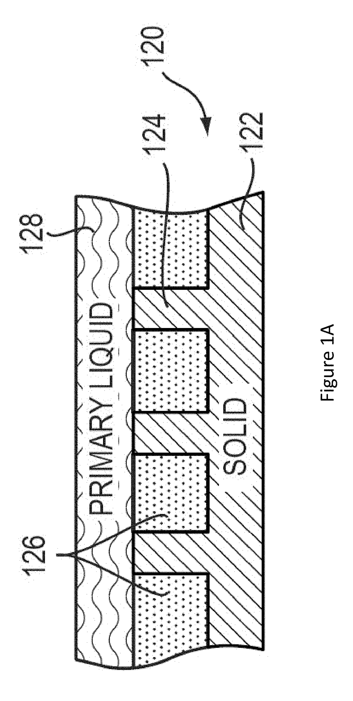
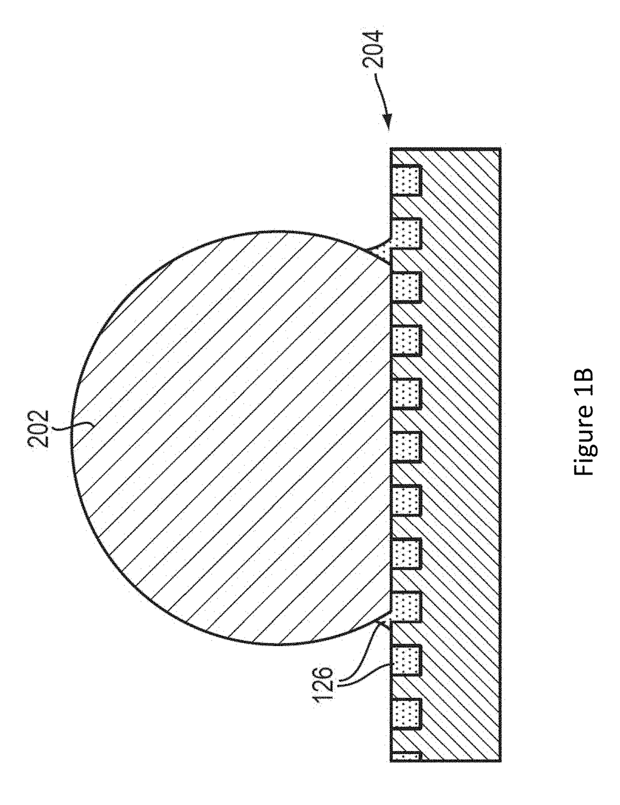
[0013]Presented herein are systems and methods for promoting, manipulating, and controlling the flow of electroactive phases of electrochemical devices by providing at least one surface (or a portion thereof) that includes a liquid lubricant impregnated within its surface features. For example, the at least one surface is a non-wetting surface that includes a liquid impregnated within a matrix of micro and / or nano-engineered features on the surface, or a liquid filling pores or other wells on the surface. In some embodiments, the liquid fills the spaces between / within the surface features, and the liquid is held between / within the surface features. In some implementations, the liquid stably is held between / within the surface feature regardless of orientation of the electrochemical device. The at least one liquid-lubricant impregnated surface may be resistant to impalement (e.g., by the flowing phase, e.g., electroactive phase). The surface may be configured to reduce viscous drag on the surface. The surface may also serve to minimize accumulation of impinging / flowing phases (e.g., electroactive phase) in some implementations.
[0014]Through proper selection of the impregnating liquid, the liquid-impregnated surfaces described herein are easily customizable to suit a desired application. In some embodiments, an existing article is retrofitted to include the at least one surface described herein.
[0027]In some embodiments, the first portion passively (e.g., the effect is a property of the surface and does not require, e.g., application of additional forces to be achieved) promotes at least one effect selected from the list consisting of: (i) increases nucleation of insoluble materials (e.g., of reacting material, e.g., insoluble lithium sulfide species) formed during operation of the electrochemical device, (ii) increases growth of insoluble materials (e.g., of reacting material, e.g., insoluble lithium sulfide species) formed during operation of the electrochemical device, (iii) increases precipitation of insoluble materials (e.g., of reacting material, e.g., insoluble lithium sulfide species) formed during operation of the electrochemical device, (iv) increases segregation of insoluble materials (e.g., of reacting material, e.g., insoluble lithium sulfide species) formed during operation of the electrochemical device at desired locations (e.g., at the electroactive region) on the internal surface of the electrochemical device.
[0028]In some embodiments, the first portion passively promotes at least one effect selected from the list consisting of: (i) inhibits nucleation (e.g., of scale or of reacting material, e.g., insoluble lithium sulfide species as discussed herein), (ii) decreases growth (e.g., of scale or reacting material, e.g., insoluble lithium sulfide species as discussed herein), (iii) inhibits precipitation (e.g., of reacting material, e.g., insoluble lithium sulfide species as discussed herein), (iv) decreases segregation (e.g., of scale or of reacting material, e.g., insoluble lithium sulfide species as discussed herein) at undesired locations (e.g., away from the electroactive region (because, e.g., if undesired nucleation takes place away from the electroactive region, battery capacity may be lost)) on the internal surface of the electrochemical device of insoluble materials formed during operation of the electrochemical device.
[0036]In some embodiments, the liquid lubricant is thermodynamically stable (e.g., wherein when surface tension of the liquid lubricant is subtracted from surface tension of an electrolyte solvent, the resulting value is greater than zero).

Problems solved by technology

Some batteries (e.g., flow batteries) have significant pumping losses due to a variety of factors, including a combination of high flow electrode viscosity, high flow velocity during operation, and / or narrow channel cross-sectional dimensions and / or long channel length.
The rheology of the flow electrodes can result in significant pumping energy losses and / or decreases in electrochemical energy efficiency (e.g., in a flow battery).

Method used


Image

  • Lubricant-impregnated surfaces for electrochemical applications, and devices and systems using same
  • Lubricant-impregnated surfaces for electrochemical applications, and devices and systems using same
  • Lubricant-impregnated surfaces for electrochemical applications, and devices and systems using same

Examples


experimental examples

Example 1

LIS for a Lithium Polysulfide Flow Battery

[0196]This example demonstrates a lithium polysulfide flow battery with a lubricant-impregnated surface (LIS).

[0197]Lithium polysulfide solutions comprising LixSy compounds dissolved in non-aqueous solvents form the basis for flowable catholytes for use in stationary or flow batteries. A representative electrolyte solution was prepared using TEG-DME (≥99%, Sigma-Aldrich), 0.5 M LiTFSI salt (≥99.95%, Sigma-Aldrich), and 1 wt % LiNO3 (ReagentPlus® grade, Sigma-Aldrich). The solution did not include the lithium polysulfide since in electrochemical tests of the lubricant and solvent system, it is necessary to evaluate side reaction currents without interference from the electrochemical couple. To design and select materials for the LIS, several candidate lubricants of various compositions were considered, as listed in Table 1 below.

[0198]Table 1 below illustrates compatibility of several candidate lubricants with the electrolyte solvent...

example 2

Surfaces Designed to be Selectively Wet by the Lubricant

[0210]This example demonstrates exemplary LISs for GIF cells. In GIF cells, lubricants should be prevented from spreading out from the LIS and over a current collector, or infiltrating the porous separator membrane.

[0211]In this example, surfaces designed to be selective to wetting by the lubricant phase of a LIS, silicone oil (10 cSt), were demonstrated. A droplet of silicone oil was placed on certain surfaces to observe whether the silicone oil spreads.

[0212]FIGS. 9A-9E illustrate results showing that surface functionalization can be used to produce surfaces that are wetting and non-wetting to silicone oil. Several surface chemistries are functionalized onto flat polydimethylsiloxane (PDMS) were examined. Un-functionalized PDMS and PDMS functionalized with trichloro(1H,1H,2H,2H-perfluorooctyl)silane were found to prevent silicone oil from spreading (e.g., wetting) in air, as shown in FIGS. 9B and 9C. On the other hand, PDMS f...


PUM

PropertyMeasurementUnit
roll-off angleaaaaaaaaaa
dynamic contact angleaaaaaaaaaa
surface energyaaaaaaaaaa

Abstract

In certain embodiments, the invention relates to an electrochemical device having a liquid lubricant impregnated surface. At least a portion of the interior surface of the electrochemical device includes a portion that includes a plurality of solid features disposed therein. The plurality of solid features define a plurality of regions therebetween. A lubricant is disposed in the plurality of regions which retain the liquid lubricant in the plurality of regions during operation of the device. An electroactive phase comes in contact with at least the portion of the interior surface. The liquid lubricant impregnated surface introduces a slip at the surface when the electroactive phase flows along the surface. The electroactive phase may be a yield stress fluid.

Description

CROSS-REFERENCE TO RELATED APPLICATIONS[0001]This application claims priority to and the benefit of, and incorporates herein by reference in its entirety, U.S. Provisional Patent Application No. 62 / 014,207, filed Jun. 19, 2014.GOVERNMENT LICENSE RIGHTS[0002]This invention was made with government support under U.S. Department of Energy Grant No. DOE-FOA-0000559, Energy Innovation Hub—Batteries and Energy Storage, and Subcontract No. 3F-31144, issued under DOE Prime Contract No. DE-AC02-06CH11357 between the United States Government and UChicago Argonne, LLC representing Argonne National Laboratory. The government has certain rights in the invention.FIELD OF INVENTION[0003]This invention relates generally to electrochemical applications, devices, and systems. More particularly, in some embodiments, the invention relates to articles and methods that promote flow (e.g., of an electroactive phase) in electrochemical systems (e.g., batteries, fuel cells, capacitors) by encapsulating or i...

Claims


Application Information

Patent Timeline
Patent Type & Authority Patents(United States)
IPC IPC(8): H01G9/145H01G9/048H01G9/035H01M12/06C09D5/03H01M8/02H01M10/02H01M10/052H01M10/36H01M8/12H01M8/18
CPCH01G9/145C09D5/037H01G9/035H01G9/048H01M8/02H01M12/06H01M8/188H01M10/02H01M10/052H01M10/36H01M8/12H01G11/06H01G11/26H01G11/38H01G11/64Y02E60/50Y02E60/10Y02E60/13
Inventor SOLOMON, BRIAN RICHMONDCHEN, XINWEICHIANG, YET-MINGVARANASI, KRIPA K.
Owner MASSACHUSETTS INST OF TECH
Why Eureka
Try Eureka