
Organic electroluminescent element

a technology of electroluminescent elements and organic materials, which is applied in the direction of luminescent compositions, energy-saving lighting, sustainable buildings, etc., can solve the problems of insufficient service life of panels, insufficient emission lifetime, and insufficient color purity in view of compatibility with wet coating processes, so as to achieve high color rendering properties, stable chromaticity, and high luminous efficiency

Inactive Publication Date: 2018-05-15
KONICA MINOLTA INC
View PDF11 Cites 4 Cited by
  • Summary
  • Abstract
  • Description
  • Claims
  • Application Information

AI Technical Summary

Benefits of technology

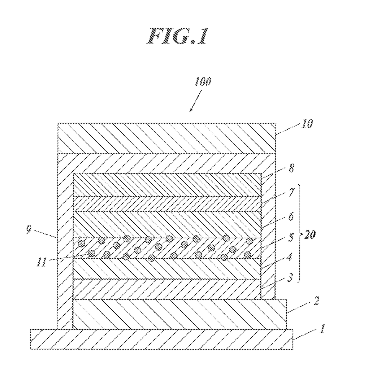
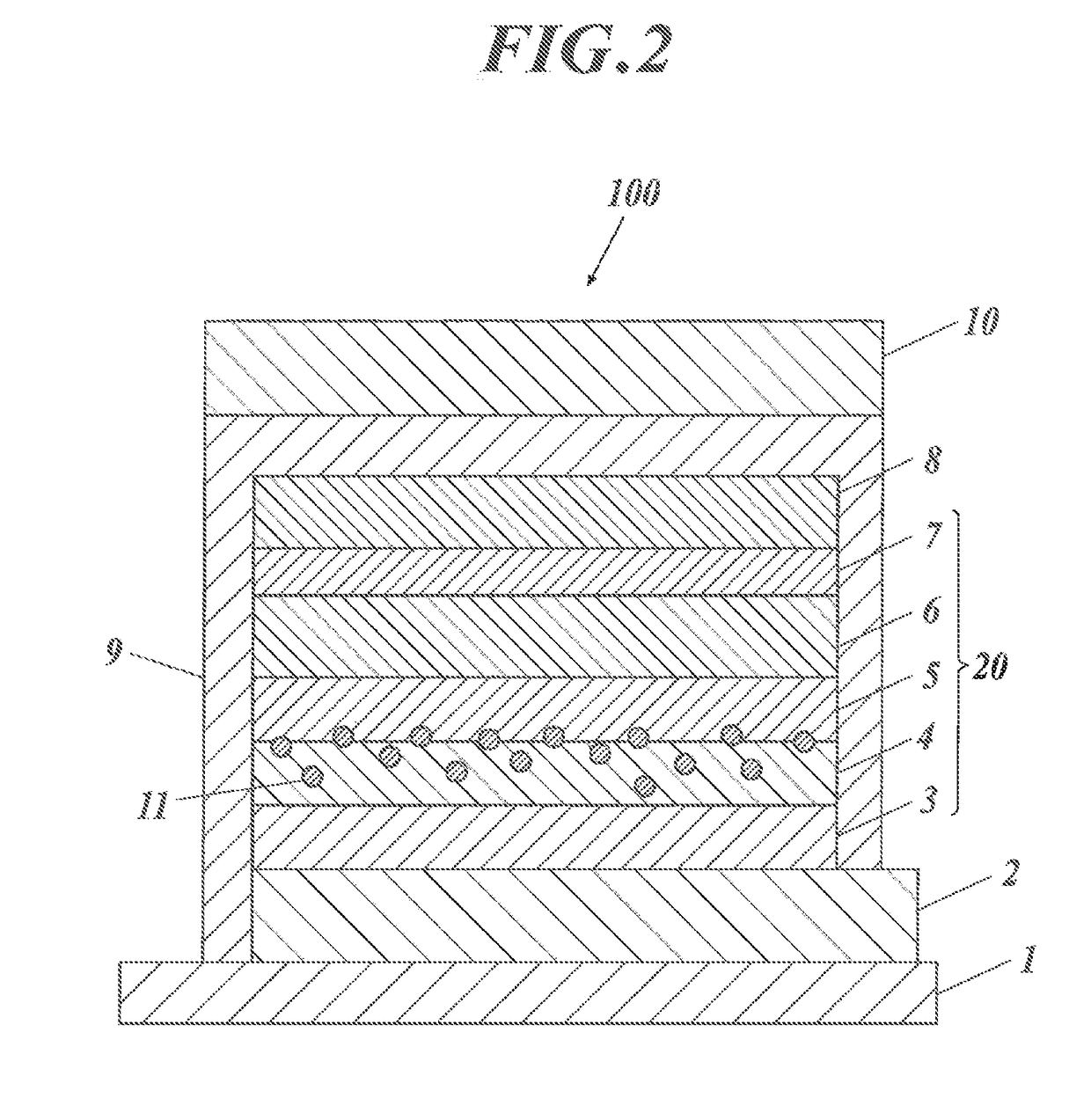
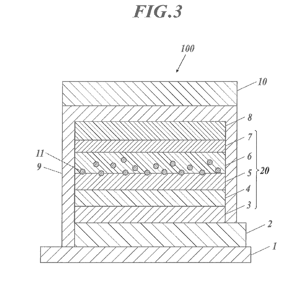
The present invention provides an organic electroluminescent element that can emit white light with high luminous efficiency for a prolonged time. This element has high color rendering properties and stable chromaticity even at a low driving voltage which cannot be achieved by any combination of known materials. Additionally, a multilayer configuration including a charge generating layer can provide a further prolonged service life with a limited increase in driving voltage compared to conventional configurations. The combination of a blue phosphorescent compound and a quantum dot in the present invention allows for efficient light emission with high color rendering properties at both the quantum dot and the blue phosphorescent compound. The blue phosphorescent compound also exhibits a significantly prolonged emission lifetime due to the robustness of the dopant. The arrangement of quantum dots adjacent to the charge generating layer facilitates charge transfer at their interface and can suppress an increase in drive voltage which is inevitable in conventional techniques.

Problems solved by technology

Unfortunately, the service life of the panels is still insufficient compared to fluorescent lamps and white light LEDs.
Although some blue phosphorescent compounds having high luminous efficiency have been discovered, these are still unsatisfactory in view of compatibility with wet coating processes, service life, and color purity at the present stage.
Unfortunately, the emission lifetime, depending on characteristics of materials in the luminous layer, is still insufficient.
Unfortunately, this technology can contain a limited amount of quantum dot material causing concentration quenching and thus exhibits insufficient brightness efficiency.
Since large amounts of various quantum dots cannot be added for the reason described above, the element exhibits unsatisfactory color rendering properties and fluctuated color indicating a color shift during a continuous drive.
Unfortunately, in both structures disclosed in Patent Literatures 3 and 4, the multiple layer configurations inevitably require high driving voltages and thus low power efficiency.

Method used


Image

  • Organic electroluminescent element
  • Organic electroluminescent element
  • Organic electroluminescent element

Examples


example 1

>

[0516]Blue luminescent organic EL elements 11 to 16 were prepared in accordance with the procedure described below.

[Preparation of Inventive Organic EL Element 11]

[0517](1.1) Preparation of Flexible Gas-Barrier Film

[0518]On an entire face (for formation of a first electrode) of a flexible poly(ethylene naphthalate) film (hereinafter referred to as PEN film) available from Teijin DuPont Films Japan Limited, an inorganic gas-barrier SiOx film was continuously formed into a thickness of 500 nm with an atmospheric plasma discharge system described in Japanese Unexamined Patent Application Publication No. 2004-68143. The resulting flexible gas-barrier film had an oxygen permeability of 0.001 ml / (m2·day·atm) or less and a moisture permeability of 0.001 g / (m2·day·atm) or less.

[0519](1.2) Formation of First Electrode Layer

[0520]Indium tin oxide (ITO) with a thickness of 120 nm was deposited by sputtering on the flexible gas-barrier film and was etched by photolithography to form a pattern ...

example 2

>

[0574]White luminescent organic EL elements 21 to 26 were prepared in accordance with the following procedure.

[Preparation of Inventive Organic EL Element 21]

[0575](1.1) Preparation of Flexible Gas-Barrier Film

[0576]On an entire face (for formation of a first electrode) of a flexible poly(ethylene naphthalate) film available from Teijin DuPont Films Japan Limited, an inorganic gas-barrier SiOx film was continuously formed into a thickness of 500 nm with an atmospheric plasma discharge system described in Japanese Unexamined Patent Application Publication No. 2004-68143. The resulting flexible gas-barrier film had an oxygen permeability of 0.001 ml / (m2·day·atm) or less and a moisture permeability of 0.001 g / (m2·day·atm) or less.

[0577](1.2) Formation of First Electrode Layer

[0578]Indium tin oxide (ITO) with a thickness of 120 nm was deposited by sputtering on the flexible gas-barrier film and was etched by photolithography to form a pattern of a first electrode (anode) layer having a...

example 3

>

[0621]Blue luminescent organic EL elements 31 to 39 were prepared in accordance with the following procedure.

[Preparation of Comparative Organic EL Element 31: Comparison Example]

[0622](1) Formation of First Electrode Layer

[0623]Indium tin oxide (ITO) with a thickness of 100 nm was formed on a glass substrate with dimensions of 100 mm by 100 mm by 1.1 mm (NA 45 made by NH Technoglass Corporation) and was patterned into an anode. The transparent substrate provided with the transparent ITO electrode was ultrasonically cleaned in isopropyl alcohol, was dried in a dry nitrogen stream, and then was cleaned in a UV ozone environment for five minutes.

[0624](2) Formation of Hole Injection Layer

[0625]A solution of 70% poly(3,4-ethylene dioxythiophene)-polyethylenesulfonate (PEDOT / PSS), CLEVIO P VP Al 4083 available from H. C. Starck) in pure water was applied by spin coating on the transparent substrate provided with the ITO transparent electrode at 3000 rpm for 30 seconds. The substrate wa...


PUM

PropertyMeasurementUnit
band gapaaaaaaaaaa
particle sizeaaaaaaaaaa
thicknessaaaaaaaaaa

Abstract

The organic electroluminescent element has a pair of electrodes and at least two organic functional layers including a light-emitting layer on a substrate. The light-emitting layer contains a host compound and a phosphorescent dopant. The light-emitting layer or the layer adjacent to the light-emitting layer contains quantum dots.

Description

CROSS REFERENCE TO RELATED APPLICATION[0001]This Application is a 371 of PCT / JP2013 / 061053 filed on Apr. 12, 2013 which, in turn, claimed the priority of Japanese Patent Application No. JP2012-096269 filed on Apr. 20, 2012 both applications are incorporated herein by reference.TECHNICAL FIELD[0002]The present invention relates to an organic electroluminescent element, in particular an organic electroluminescent element having high luminous efficiency, prolonged emission lifetime, and excellent color rendering properties.BACKGROUND ART[0003]In recent years, organic electroluminescent elements composed of organic materials (hereinafter, also referred to as organic EL elements) have promise as inexpensive large-area full-color display devices of solid emission types and writing light-source arrays and thus have been under extensive research and development.[0004]Organic EL elements are full solid state elements of thin film types, each including a single or multiple organic functional ...

Claims


Application Information

Patent Timeline
Patent Type & Authority Patents(United States)
IPC IPC(8): C09K11/06H01L51/50C09K11/88H01L51/00H10K99/00
CPCH01L51/502C09K11/06C09K11/88H01L51/0072H01L51/0073H01L51/0085H01L51/5004H01L51/5016C09K2211/185H01L51/0097Y02B20/181Y02B20/00H10K85/6574H10K85/342H10K77/111H10K85/6572H10K50/11H10K2101/40H10K50/115H10K2101/10C09K11/08C09K11/54C09K11/59C09K11/62C09K11/66H05B33/14
Inventor IKEMIZU, DAIIIJIMA, TAKAYUKIHATTORI, TAKAMUNEOKUBO, YASUSHITAKA, HIDEO
Owner KONICA MINOLTA INC
Learn More