Confocal microscope apparatus and photographing apparatus for confocal microscope

a confocal microscope and microscope technology, applied in the field of confocal microscope apparatus and photographing apparatus, can solve the problems of low cost performance, poor balance between apparatus cost and performance, and often limited application to real-time observation, and achieve the effect of suppressing the noise of pinhole patterns

Inactive Publication Date: 2007-07-31
OLYMPUS OPTICAL CO LTD
View PDF8 Cites 6 Cited by
  • Summary
  • Abstract
  • Description
  • Claims
  • Application Information

AI Technical Summary

Benefits of technology

[0036]According to the present invention, even if the exposure time changes depending on the specimen brightness, the total number of turns of the disk within the exposure time can be kept constant. The exposure start and end timings can be synchronized with the

Problems solved by technology

However, the application is often limited to real-time observation at a video rate or more for the movement of a cell injected with a fluorescent indicator such as Ca ions or pH.
This arises from marketing factors such as a small number of manufacturers for confocal microscopes using disk scanners, resulting in few product variations, and poor balance between apparatus cost and performance, resulting in low cost performance.
That is, this technique does not consider use conditions for photographing a still image, and particularly photographing conditions under which the exposure time changes over a wide range of several hundredth sec to several ten sec in accordance with the specimen brightness.
Again, however, the image sensing device is limited to the CCD camera 201 using a NTSC signal, and does not consider any applic

Method used


Image

  • Confocal microscope apparatus and photographing apparatus for confocal microscope
  • Confocal microscope apparatus and photographing apparatus for confocal microscope
  • Confocal microscope apparatus and photographing apparatus for confocal microscope

Examples


first embodiment

[0047](First Embodiment)

[0048]The first embodiment will be described, where the present invention is applied to a confocal microscope apparatus including an erect microscope and a photography.

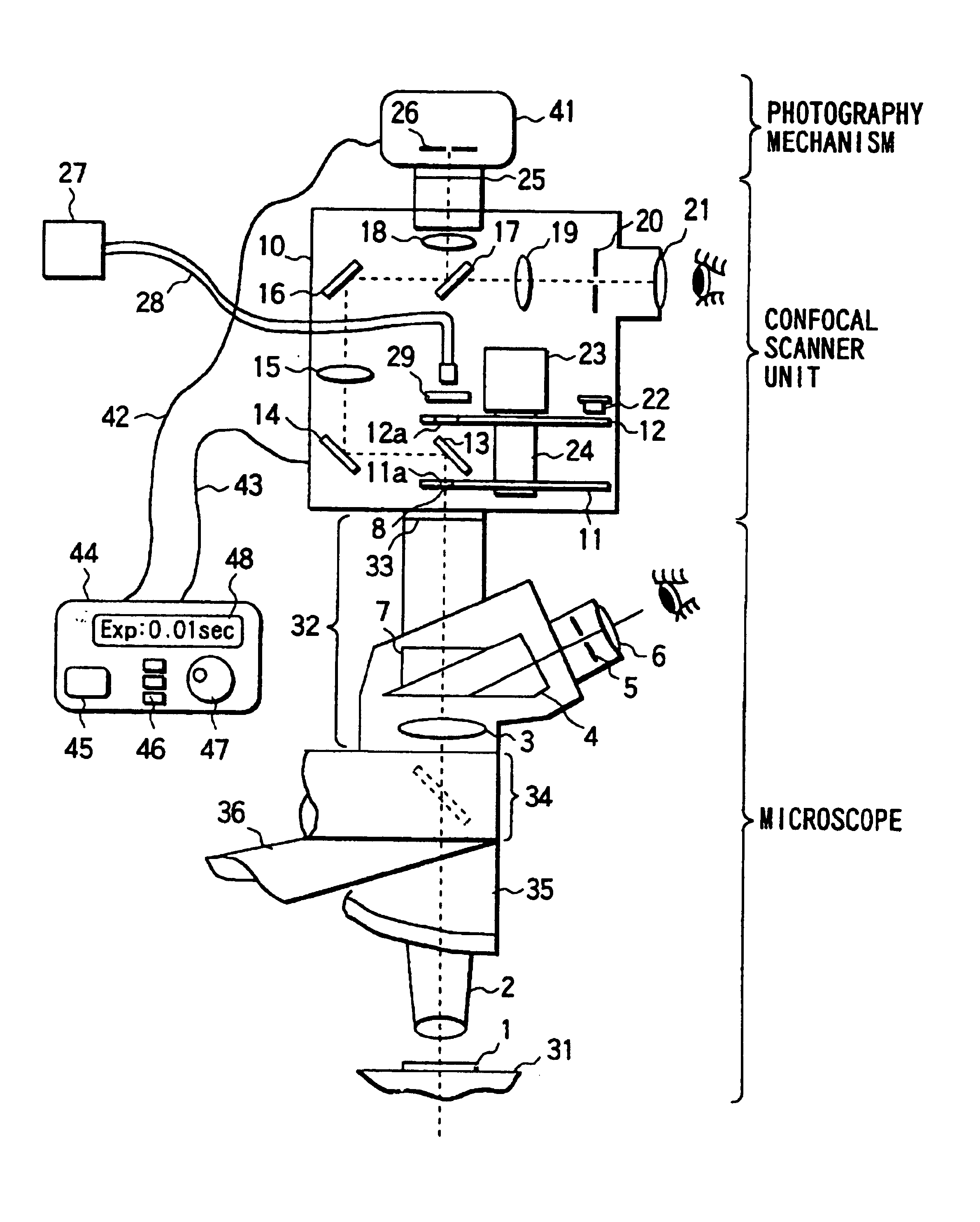
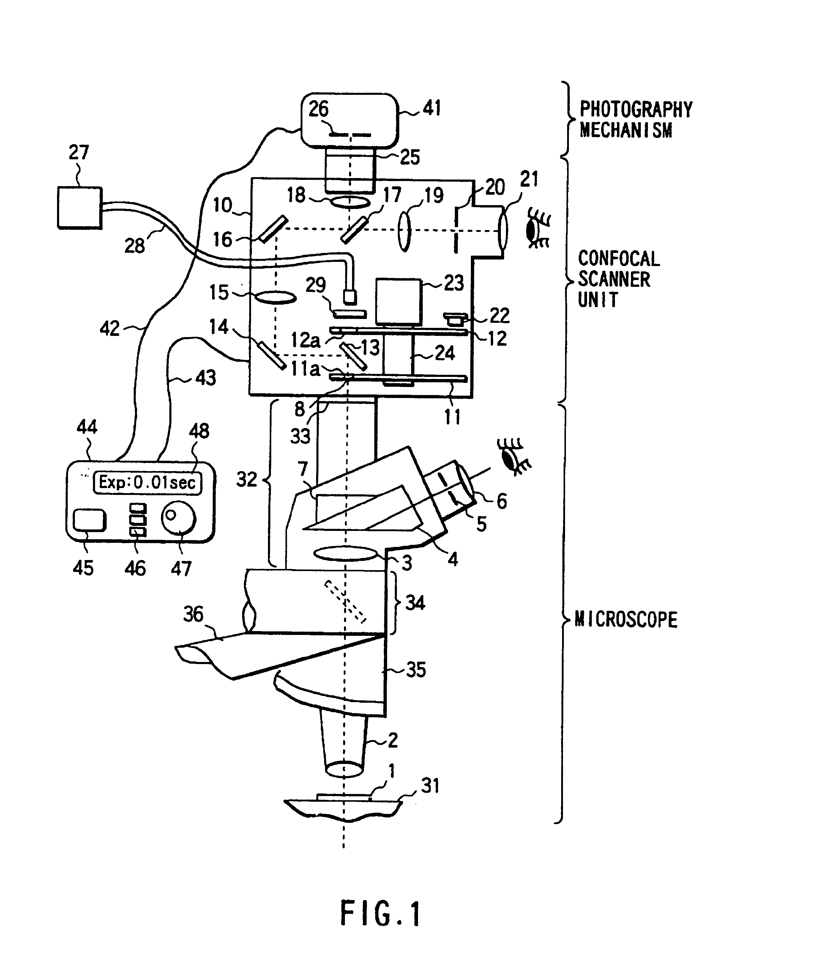
[0049]FIG. 1 shows the arrangement of the whole optical system of the confocal microscope apparatus. The optical system is made up of three parts, photography mechanism, confocal scanner unit 10, and microscope.

[0050]The microscope is an erect microscope having a triple-lens barrel 32 with a photographing optical path. FIG. 1 shows an only upper observation optical system from the upper surface of a stage 31. The photography mechanism contains a camera main body 41 and a control unit 44. The camera main body 41 and control unit 44 are connected by a cable 42 in two ways. The control unit 44 and confocal scanner unit 10 are connected by a cable 43 in two ways.

[0051]In the triple-lens barrel 32, a 30° prism 4 and a cylindrical prism 7 are selectively exchangeably inserted in the optical path on a...

second embodiment

[0071](Second Embodiment)

[0072]The second embodiment will be described, where the present invention is applied to a confocal microscope apparatus including an erect microscope and a photography.

[0073]The arrangement of an optical system in the second embodiment is the same as that described with reference to FIG. 1.

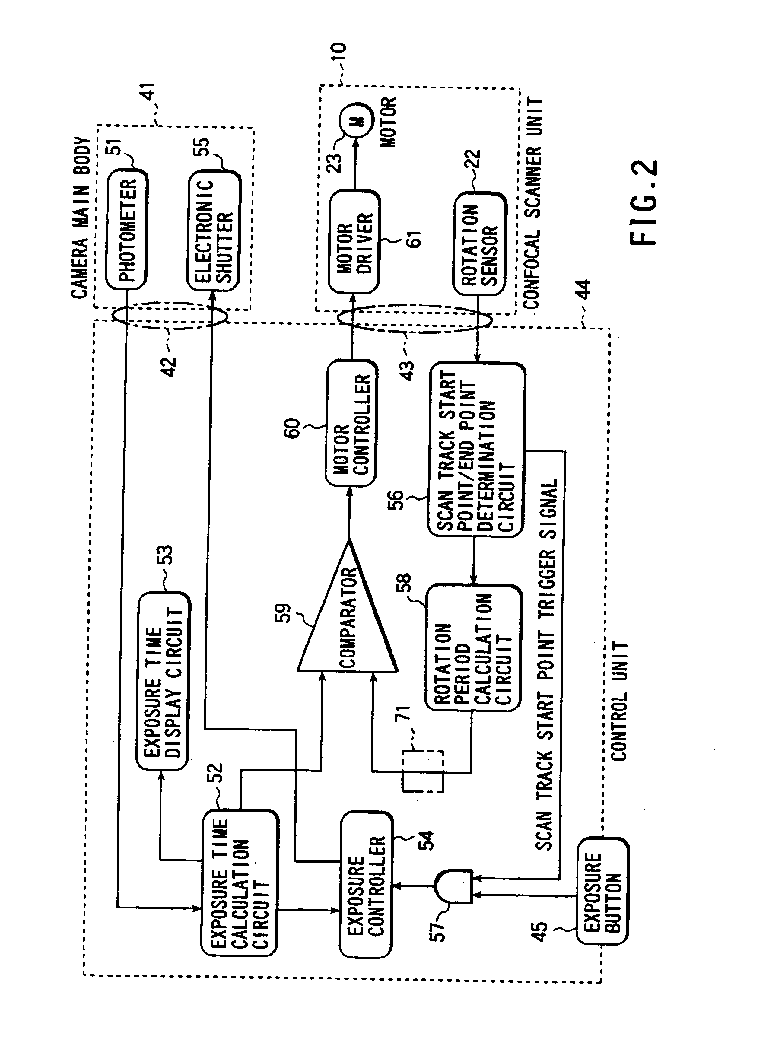
[0074]FIG. 3 is a block diagram showing the arrangement of an electronic circuit according to the second embodiment provided to the control unit 44, camera main body 41, and confocal scanner unit 10. The electronic circuit shown in FIG. 3 is basically the same as that shown in FIG. 2 except for the following difference.

[0075]The second embodiment is arranged in consideration of a case where the user observes a specimen with the naked eye via an eyepiece lens 21 without using any camera main body 41, and a case where a video camera device (not shown) is mounted instead of the camera main body 41. In mounting the video camera device, a video sync signal equivalent to a vert...

third embodiment

[0085](Third Embodiment)

[0086]The third embodiment will be described, where the present invention is applied to a confocal microscope apparatus including an erect microscope and a photography.

[0087]The arrangement of an optical system in the third embodiment is the same as that described with reference to FIG. 1.

[0088]FIG. 4 is a block diagram showing the arrangement of an electronic circuit according to the third embodiment provided to the control unit 44, camera main body 41, and confocal scanner unit 10. The electronic circuit shown in FIG. 4 is basically the same as that shown in FIG. 2 except for the following difference.

[0089]In the third embodiment, a comparator 59′ receives a rotational period limit signal representing the upper limit of the rotational period of the motor 23 from a rotational speed reference circuit 65. A laser intensity controller 66 which has received a signal outputted from the comparator 59′ appropriately outputs a laser intensity control signal to the m...


PUM


Abstract

A confocal microscope apparatus includes a disk scanner for scanning a specimen with a laser beam, and camera main body for photographing a still image. An exposure time calculation circuit is arranged to generates an exposure time signal for the camera main body. A rotation sensor, a scan track start point/end point determination circuit, and a rotation period calculation circuit are arranged to generate a rotational period signal for the disk scanner. A comparator compares the exposure time signal with the rotational period signal, so that a motor controller and a motor driver control rotation of a motor of the disk scanner by a comparison output from the comparator.

Description

BACKGROUND OF THE INVENTION[0001]The present invention relates to a confocal microscope apparatus and a photographing apparatus for a confocal microscope, for photographing a confocal image of a microscope specimen.[0002]In recent years, confocal microscopes have rapidly spread owing to their improved effects in optical performance called confocal effects including a sectioning effect along the optical axis and a super-resolution effect. These confocal microscopes can be roughly classified into two, single-beam type (fixed-pinhole type / a single pinhole) and multi-beam type (movable pinhole type / a plurality of pinholes) on the basis of the scanning principle and the basic arrangements of a scanner and an optical system.[0003]The single-beam type confocal microscope drives a laser beam for scanning, using a galvanometer mirror or an optical deflector such as an acousto-optical deflector (AOD). The-multi-beam type confocal microscope uses a rotating disk scanner (to be referred to as a...

Claims


Application Information

Patent Timeline
IPC IPC(8): G02B21/06G01B11/24G02B21/00H04N5/225G02B21/18G02B21/36
CPCG02B21/0044G02B21/008
Inventor KITAGAWA, HISAO
Owner OLYMPUS OPTICAL CO LTD
Why Eureka
Try Eureka