
Zero-current switching power factor corrector with energy recovery

A technology for switching power and energy recovery, applied in high-efficiency power electronic conversion, output power conversion devices, electrical components, etc., can solve the problems of increasing switching loss, large switching loss, and poor reliability of components

Inactive Publication Date: 2007-09-26
ACBEL POLYTECH INC
View PDF2 Cites 0 Cited by
  • Summary
  • Abstract
  • Description
  • Claims
  • Application Information

AI Technical Summary

Problems solved by technology

[0004] For example, the TW Announcement No. 279514 "Zero-Current Switching Circuit for Power Regulator" new patent case, which was approved for the same application, has a creative background that reviews traditional power regulators (power factor correctors). A kind of switching power supply, its advantage is that the number of components used is few, and production cost is lower, but its improved efficiency is only about 85%, and because the recovery current of diode (73) is quite large, will increase switching loss, causes The electromagnetic interference (EMI) is also very considerable, and because of the sharp reverse recovery current passing through the dynamic components when switching, it is easy to damage the components, so the reliability of the components is the worst
[0005] It also provides another kind of switching power supply, which replaces the aforementioned diode (73) with some series-connected Schockley diodes (74) (Shockley Diode) and resistors and capacitors. In addition, because the reverse recovery current of the Schottky diode (74) is small, the electromagnetic interference it may cause is also small, but its efficiency is still low, only about 87%. The series connection increases the forward voltage drop, resulting in large switching loss, and its withstand voltage is not easy to balance, and it is easy to cause damage, so the reliability of its components is poor, and the manufacturing cost is high
As for its zero-voltage switching power supply, the efficiency can reach 92%, and because the reverse recovery current is recycled through the zero-voltage switching circuit, the electromagnetic interference is small, but the zero-voltage switching circuit will produce a sharp switching greater than the input current Therefore, it is impossible to minimize electromagnetic interference. In addition, this zero-voltage switching power supply uses the largest number of parts, and because of complex control, there are also sharp currents passing through the active components, so the reliability of the components is poor.

Method used

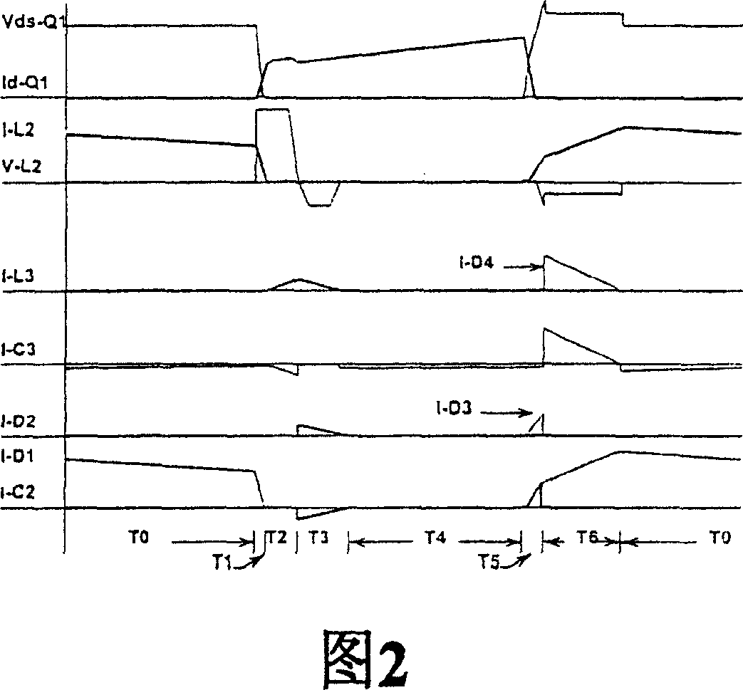
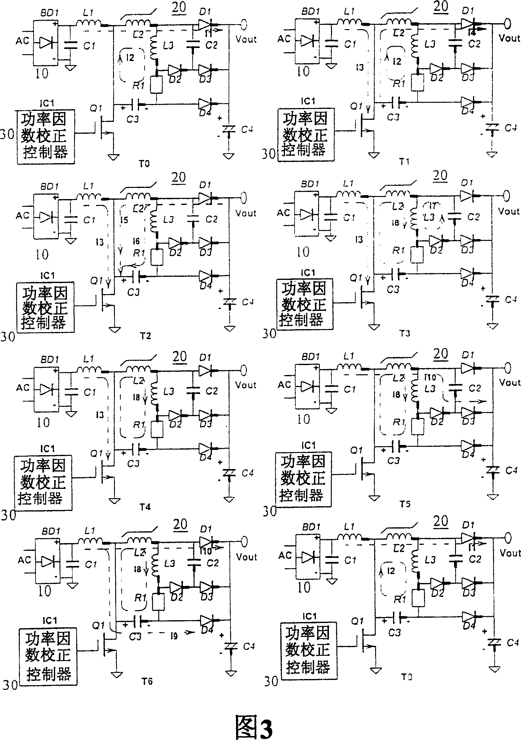

Image

  • Zero-current switching power factor corrector with energy recovery
  • Zero-current switching power factor corrector with energy recovery
  • Zero-current switching power factor corrector with energy recovery

Examples


Embodiment Construction

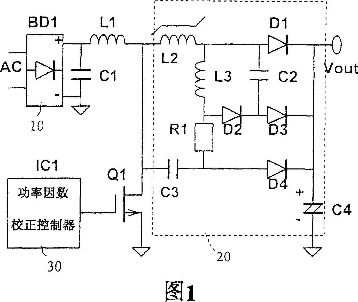
[0034] Regarding the specific circuit structure of a preferred embodiment of the present invention, please refer to shown in Fig. 1, it makes a power factor corrector in a bridge rectifier 10 and a power output terminal V out Separated with a filter capacitor C 1 , an energy storage inductor L 1 And an energy conversion circuit 20; and the output terminal of a power factor correction controller 30 is passed through a metal oxide semiconductor field effect transistor Q 1 Connected to the energy storage inductor L 1 Between the energy conversion circuit 20; wherein: the power factor correction controller 30 is composed of a pulse width modulation circuit. Again, the energy conversion circuit 20 includes:

[0035] A saturated reactance L 2 , with a power diode D 1 Connected in series with the aforementioned energy storage inductance L 1 with the supply output V out between;

[0036] An energy recovery capacitor C 2 , through an inductor L 3 , a diode D 2 In the saturat...


PUM


Abstract

A filter capacitor, an inductance of stored energy and an energy conversion circuit are setup between bridge rectifier and output end of power source. Output end of power factor calibration controller through a MOS field-effect transistor is connected between the inductance of stored energy and the energy conversion circuit. The energy conversion circuit through saturation reactance, capacitor and inductance of stored energy assorted with several diodes constitute different current loops at different operating periods in order to reclaim energy in reverse direction. The said energy reclaimed through steps of storing energy and discharging electricity is recycled in order to raise work efficiency of power factor calibration controller.

Description

technical field [0001] The invention relates to a zero-current switching power factor corrector with energy recovery, especially a zero-current switching power factor corrector that can recover the reverse energy generated during transition and reuse it through energy storage, discharge and other steps. Background technique [0002] At present, the existing switching power converter generally includes a power factor corrector, a boost conversion circuit controlled by the aforementioned power factor corrector, a forward output circuit connected and controlled by the power factor corrector, and a Auxiliary power supply circuit for wide modulation function. Wherein: the power factor correction controller is used to control the aforementioned boost conversion circuit and forward output circuit, and cooperates with the output circuit to stabilize the power output. [0003] The traditional power factor corrector converts energy from the input terminal to the output terminal throu...

Claims


Application Information

Patent Timeline
IPC IPC(8): H02M1/14
CPCY02B70/1491Y02B70/10Y02P80/10
Inventor 林国藩李鸿钦
Owner ACBEL POLYTECH INC
Learn More