Methods for producing silicon nitride films and silicon oxynitride films by thermal chemical vapor deposition

A technology of silicon nitride thin film and silicon nitride oxide, which is applied in gaseous chemical plating, semiconductor/solid-state device manufacturing, electrical components, etc. And other issues

Inactive Publication Date: 2007-11-07
LAIR LIQUIDE SA POUR LETUDE & LEXPLOITATION DES PROCEDES GEORGES CLAUDE
View PDF7 Cites 3 Cited by
  • Summary
  • Abstract
  • Description
  • Claims
  • Application Information

AI Technical Summary

Problems solved by technology

However, this document only reported the mechanism of silicon nitride growth, and did not make any evaluation on the performance of the prepared silicon nitride film.
In addition, the literature does not mention the use of TSA to form silicon oxynitride films

Method used


Image

  • Methods for producing silicon nitride films and silicon oxynitride films by thermal chemical vapor deposition
  • Methods for producing silicon nitride films and silicon oxynitride films by thermal chemical vapor deposition
  • Methods for producing silicon nitride films and silicon oxynitride films by thermal chemical vapor deposition

Examples


preparation example Construction

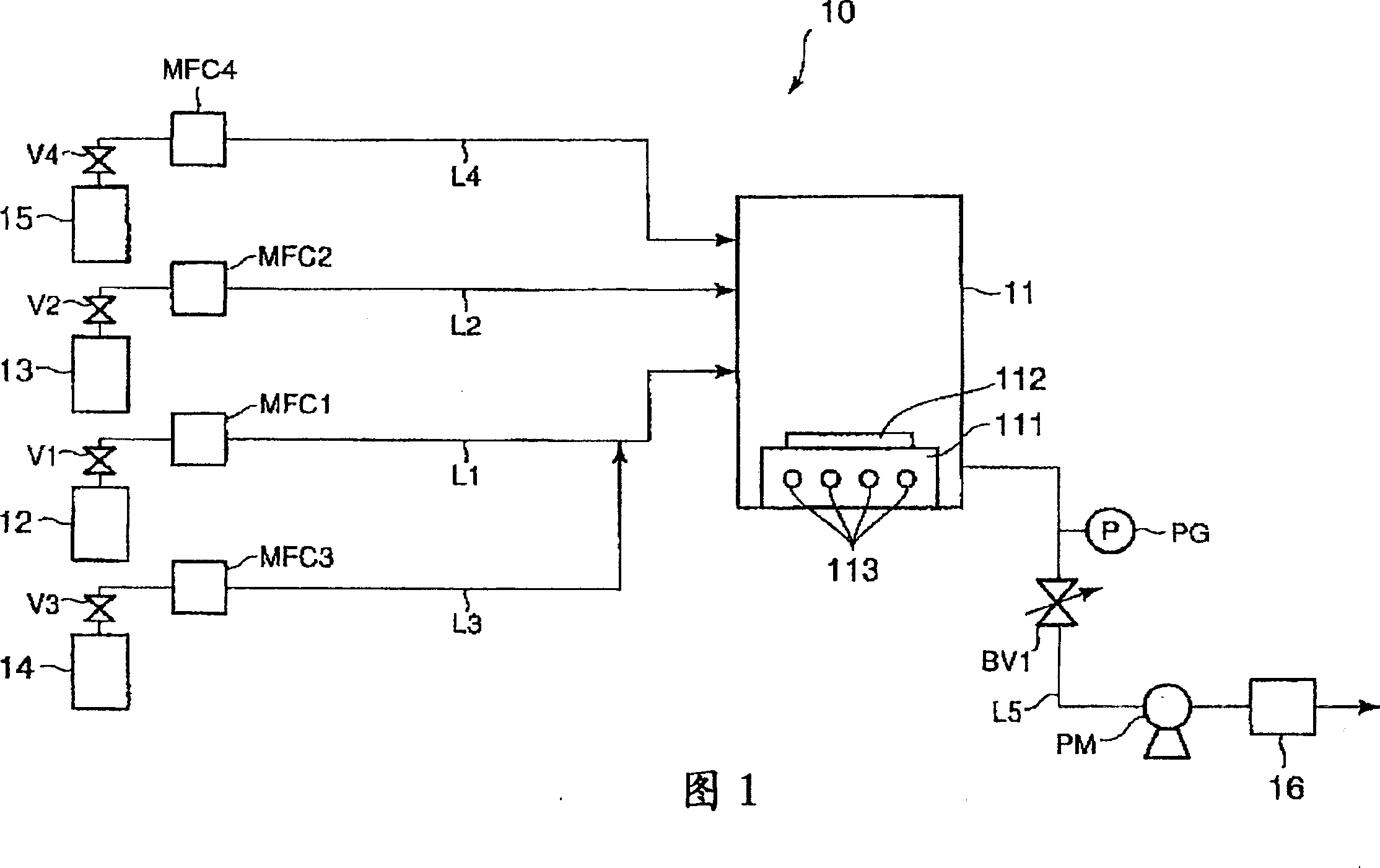
[0070] The oxygen source gas source 15 used in the preparation process of the silicon oxynitride film includes a sealed container containing the oxygen source gas. An oxygen source gas is introduced from its source 15 and into the CVD reaction chamber 11 through an oxygen source gas feed line L4. A shut-off valve V4 is installed in the feed pipe L4 and a flow rate controller such as a mass flow controller MFC4 is installed downstream thereof. The oxygen source gas is controlled to a predetermined flow rate by a mass flow controller MFC4 and introduced into the CVD reaction chamber 11 .

[0071] The outlet of the CVD reaction chamber 11 is connected to an exhaust gas treatment device 16 through a line L5. The waste gas treatment device 16 removes substances such as by-products and unreacted materials, and the gas purified by the waste gas treatment device 16 is discharged from the system. In the line L5 are installed a pressure sensor PG, a pressure regulator such as a butter...

Embodiment 1

[0082] A fabrication facility as shown in Figure 1 (but without the oxygen source gas feed system) was used in this example. Ammonia gas and TSA gas were introduced into a CVD reaction chamber in which a silicon substrate was placed, and a silicon nitride film was formed on the silicon substrate under the following conditions.

[0083] Ammonia flow rate: 40sccm

[0084] TSA gas flow rate: 0.5sccm

[0085] Pressure in CVD reaction chamber: 1 Torr

[0086] Reaction temperature: 640°C

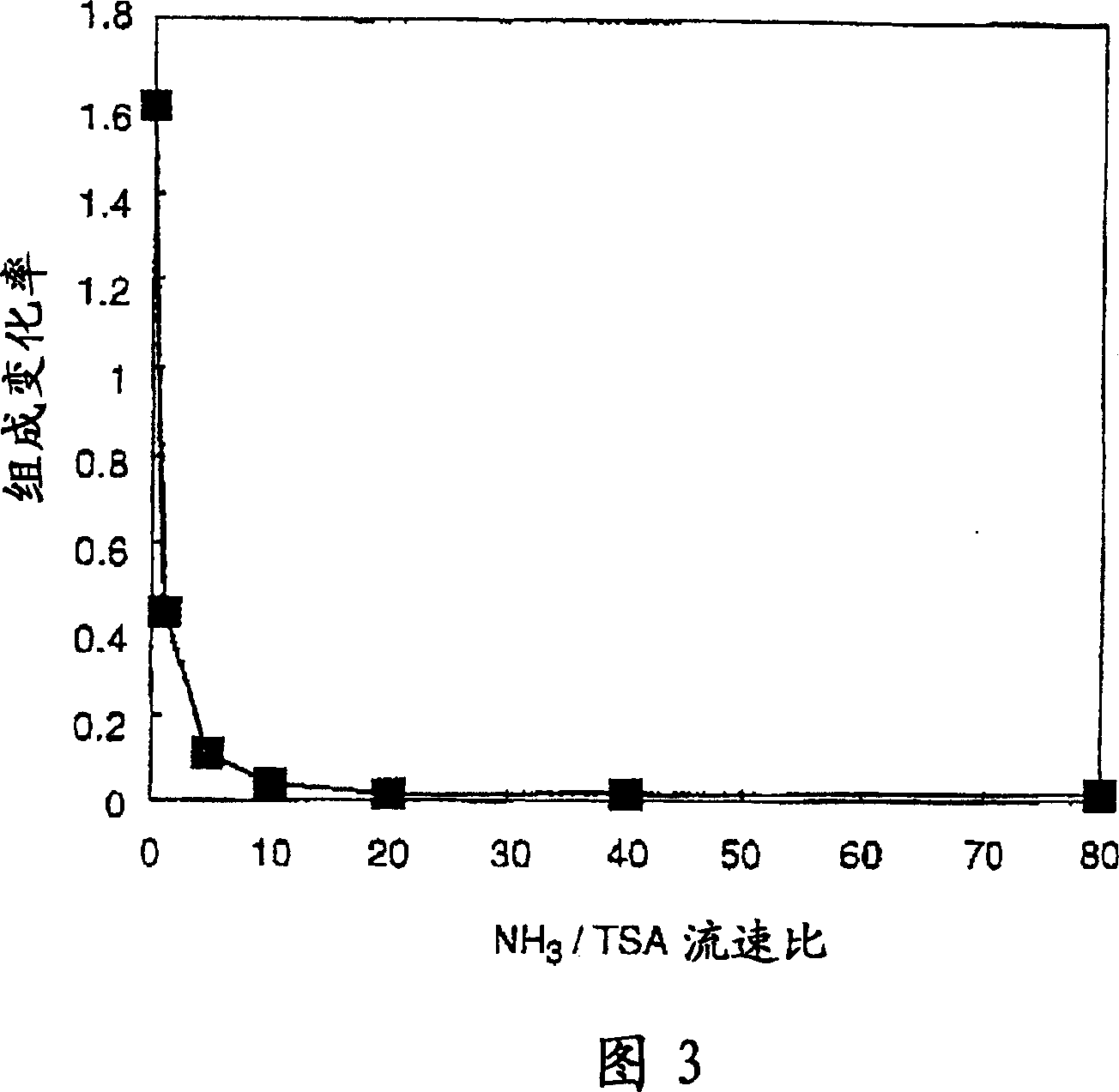
[0087] The composition of the obtained silicon nitride film was determined by Auger spectroscopy to be Si 0.81 N. The deposition (growth) rate of the silicon nitride film was 17 angstroms / minute. NH in this example 3 / TSA flow rate ratio was 80, and a stable film composition was obtained.

Embodiment 2

[0089] A fabrication facility as shown in Figure 1 (but without the oxygen source gas feed system) was used in this example. Ammonia gas and TSA gas were introduced into a CVD reaction chamber in which a silicon substrate was placed, and a silicon nitride film was formed on the silicon substrate under the following conditions.

[0090] Ammonia flow rate: 40sccm

[0091] TSA gas flow rate: 4sccm

[0092] Pressure in CVD reaction chamber: 1 Torr

[0093] Reaction temperature: 560°C

[0094] The composition of the obtained silicon nitride film was determined by Auger spectroscopy to be Si 1.04 N. The deposition (growth) rate of the silicon nitride film was 6 angstroms / minute. NH in this example 3 / TSA flow rate ratio was 10, and a stable film composition was obtained.


PUM


Abstract

Silicon nitride film is formed on substrate by feeding trisilylamine and ammonia into a CVD reaction chamber that contains a substrate. The ammonia gas / trisilylamine gas flow rate ratio is set to a value of at least about 10 and / or the thermal CVD reaction is run at a temperature no greater than about 600° C. Silicon oxynitride is obtained by introducing an oxygen source gas into the CVD reaction chamber. This method avoids the production of ammonium chloride and / or the incorporation of carbonaceous contaminants which are detrimental to the quality of the deposited film.

Description

technical field [0001] The present invention relates to methods of manufacturing silicon nitride films and silicon oxynitride films. More specifically, the present invention relates to methods of manufacturing silicon nitride films and silicon oxynitride films by thermal chemical vapor deposition (thermal CVD). Background technique [0002] Silicon nitride films have excellent blocking properties and excellent oxidation resistance, and are therefore used in the manufacture of semiconductor components, for example as etch stop layers, spacer layers or gate dielectric layers, and in oxide / nitride stacks . [0003] Plasma-enhanced CVD (PECVD) and low-pressure CVD (LPCVD) are currently the main methods used to grow silicon nitride films. [0004] Usually, by adding a silicon source (usually silane) and a nitrogen source (usually ammonia, but nitrogen has been used more recently) between a pair of parallel plate electrodes, and at low temperature (about 300°C) and low pressure ...

Claims


Application Information

Patent Timeline
Patent Type & Authority Patents(China)
IPC IPC(8): H01L21/318C23C16/34C23C16/30C23C16/42H01L21/314
CPCH01L21/3145H01L21/0214H01L21/0217C23C16/308H01L21/02219C23C16/345H01L21/3185H01L21/02271
Inventor C·迪萨拉J-M·吉拉尔木村孝子玉置直树佐藤裕辅
Owner LAIR LIQUIDE SA POUR LETUDE & LEXPLOITATION DES PROCEDES GEORGES CLAUDE
Why Eureka
Try Eureka