Two way DC converter controlled by one-end voltage stable, one-end current stable phase shift plus PWM and its control method

A bidirectional DC conversion and closed-loop control technology, which is applied in the direction of converting DC power input to DC power output, control/regulation systems, and conversion equipment with intermediate conversion to AC, can solve the problem of reducing transformer utilization, narrowing the ZVS range, The two-way free flow control of energy has no problems such as a simple and reliable control strategy to achieve the effects of reducing circulation loss, improving efficiency, and excellent steady-state and dynamic characteristics

Inactive Publication Date: 2008-10-08
NANJING UNIV OF AERONAUTICS & ASTRONAUTICS
View PDF5 Cites 1 Cited by
  • Summary
  • Abstract
  • Description
  • Claims
  • Application Information

AI Technical Summary

Problems solved by technology

In order to meet the above requirements, there are two types of converters in the prior art: a two-terminal voltage type high-power dual active full-bridge bidirectional DC-DC converter and a current-voltage type dual active half-bridge bidirectional DC-DC converter. The symmetrical structure realizes the two-way transfer of energy and the zero-voltage operation of all switching tubes, but the voltage spikes in the power devices of the current source half-bridge have not been suppressed, and there are increased circulating losses and The narrowing of the ZVS range offsets the contribution of soft switching to conversion efficiency, thus limiting the application of traditional phase shift control bidirectional DC-DC converters in occasions with large terminal voltage fluctuations
Patent 02112194.X proposes a bidirectional DC-DC converter based on an asymmetric structure, using PWM plus phase shift control technology to achieve voltage matching at both ends of the transformer, but produces DC bias of the transformer, reducing the utilization of the transformer
In addition, due to the differences in the circuit models of the two-way energy conversion of the converter, there is no simple and reliable control strategy for the two-way free flow control of energy.

Method used


Image

  • Two way DC converter controlled by one-end voltage stable, one-end current stable phase shift plus PWM and its control method
  • Two way DC converter controlled by one-end voltage stable, one-end current stable phase shift plus PWM and its control method
  • Two way DC converter controlled by one-end voltage stable, one-end current stable phase shift plus PWM and its control method

Examples


specific example

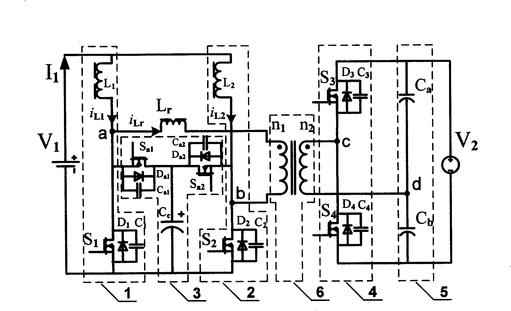
[0028] A specific example of the present invention is as follows: terminal voltage V 1 =22-32V, V 2 =270V; rated power P N =1.5kW; Transformer ratio n 2 : n 1 =2.1, leakage inductance Lr=1.2μH; inductance L 1 =L 2 =15μH; clamp capacitor C c =3μF; Divider capacitor C a =C b =470μF; switch tube S 1 , S 2 : APT20M11JFLL, switch tube S 3 , S 4 : APT77N60JC3, auxiliary pipe S a1 , S a2 : APT20M16LFLL; switching frequency f = 100kHZ. attached Figure 6-9 It is the specific experimental waveform diagram of this example, wherein, the appended Figure 6 It is the voltage and current experimental waveform diagram of transformer two terminals under different battery voltages of the present invention and leakage inductance current; Accompanying drawing 7 (a)-(c) is the voltage and current experimental waveform diagram of each switch tube when the Boost mode work of the present invention; Figure 8 (a)-(c) is the voltage and current experiment wave figure of each switching ...


PUM


Abstract

This invention relates to a 2-way DC convertor by phase shift of voltage regulation at one end and current stabilizing at the other plus PWM control and a control method, in which the 2-way DC converter includes a primary circuit, a switch control and a close-ring control, the primary circuit is composed of inductor L1, a switch tube S1 and serial branch 1, inductor L2, switch tube S2 and serial branch2, two auxiliary switch tubes Sa1 and Sa2, a clamp capacitor Cc and a composite branch 3, switch tubes S3 and S4 and serial branch 4, bleeder capacitor Ca and Cb, a serial branch 5 and an isolation transformer, the switch control circuit is composed of a phase shift control chip, a monostable trigger8 and a PWM control chip 9, the close ring control part is made up of a phase shift angle close ring control loop and a duty ratio close ring control loop, characterizing that: 1, suppressing the voltage peak of the tube, 2, reducing the circumfluence loss of the converter to guarantee the soft switch in the total load sphere, 3, the uncoupling control of the phase shift angle and the duty ratio realizes 2-way free flow of energies.

Description

1. Technical field [0001] The bidirectional DC converter and its control method of the present invention belong to a bidirectional DC-DC converter and a control method for bidirectional free flow of energy. 2. Technical Background [0002] In a typical uninterruptible power supply system, a battery is used as an energy storage element. When the external power supply is normal, the battery is charged by the external power supply. Once the external power supply is abnormal, the battery provides electric energy. In the aircraft high-voltage DC power supply system, when the main power supply (270VDC) is normal, the main power supply charges the battery (28V) through the bidirectional DC-DC converter, and supplies power to the 28V important load. The DC converter supplies the 270V critical load. In the above-mentioned application occasions, high-low voltage conversion is involved, and electrical isolation is generally required. In order to meet the above requirements, there are...

Claims


Application Information

Patent Timeline
Patent Type & Authority Patents(China)
IPC IPC(8): H02M3/28H02M3/335
CPCY02B70/1491Y02B70/10
Inventor 肖华锋谢少军
Owner NANJING UNIV OF AERONAUTICS & ASTRONAUTICS
Why Eureka
Try Eureka