
Method for non-vacuum melting and casting Cu-Cr-Zr alloy

A non-vacuum smelting, cu-cr-zr technology, used in the processing, smelting and casting of Cu-Cr-Zr alloys, can solve the problem of inability to measure components, adjust components, raw material components and impurities High content requirements, high requirements for furnace body sealing and other problems, to achieve the effects of large-scale production, high cost, and difficult large-scale production

Inactive Publication Date: 2008-10-15
CHINA NON-FERROUS METALS PROCESSING TECH CO LTD
View PDF1 Cites 2 Cited by
  • Summary
  • Abstract
  • Description
  • Claims
  • Application Information

AI Technical Summary

Problems solved by technology

[0003] However, the method of vacuum smelting Cu-Cr-Zr alloy has the following problems: ①Due to the high degree of vacuum required in the smelting process of the vacuum furnace, the requirements for the tightness of the furnace body are very high, and composition measurement, composition adjustment and Slag pulling and other operations, so the requirements for the composition and impurity content of raw materials are very high; ②Vacuum smelting generally does not adopt the method of rapid cooling, the ingot is prone to crystal coarsening, and cracks are prone to appear in the deformation process, which reduces the thickness of the strip. Yield; ③The discontinuous operation of the vacuum furnace itself makes it only possible to carry out small-scale production, and cannot carry out continuous large-scale production, which limits its industrialization prospects

Method used


Image

  • Method for non-vacuum melting and casting Cu-Cr-Zr alloy
  • Method for non-vacuum melting and casting Cu-Cr-Zr alloy
  • Method for non-vacuum melting and casting Cu-Cr-Zr alloy

Examples


Embodiment 1

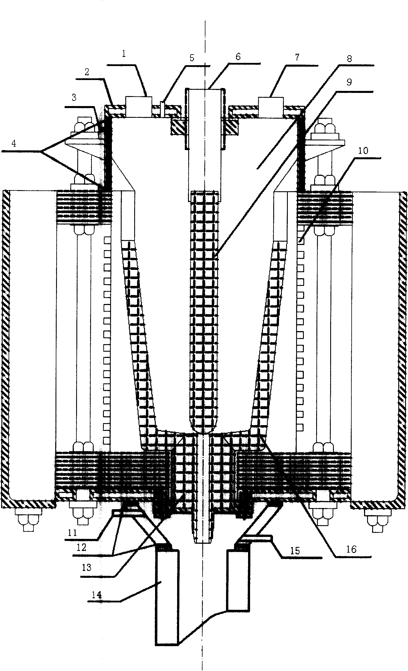
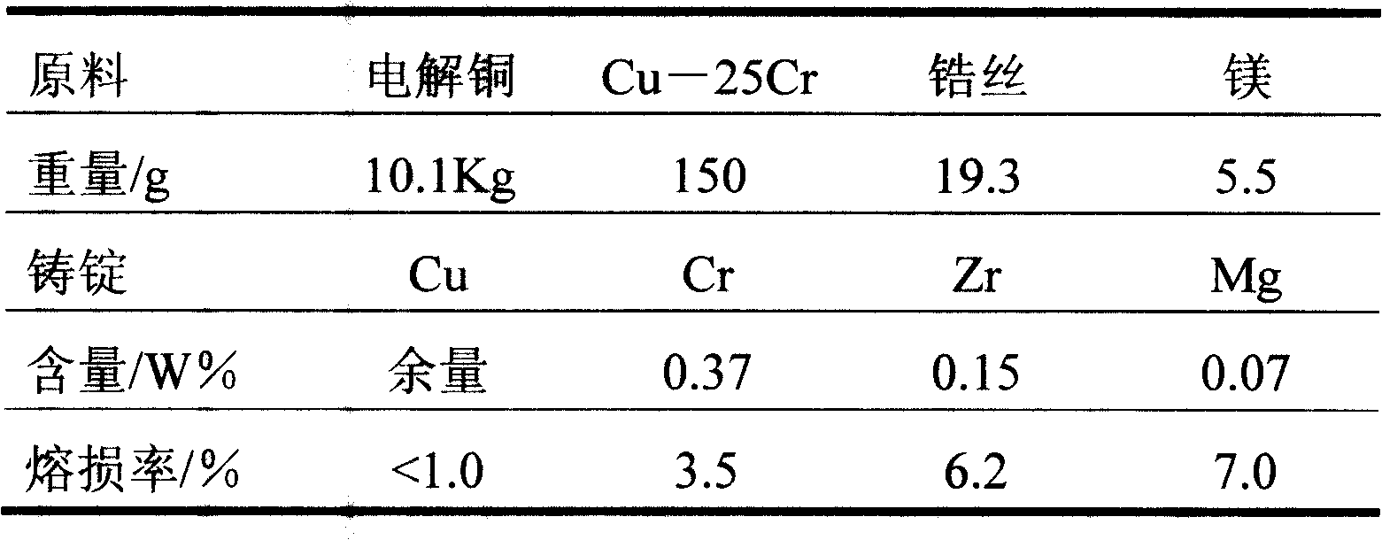
[0020] The raw materials of electrolytic copper, copper-chromium intermediate alloy and zinc are respectively taken, and the amount of materials taken is shown in Table 1, and loaded into the furnace 8 from the feeding port 7, so that it is contained in the crucible 16; the furnace cover 2 can also be opened to directly add raw materials. Cover the feeding port 7 and the observation window 1, open the protective gas valve, and pass in argon gas from the upper air inlet 3 until the air is discharged from the upper gas outlet 5, the protective gas is filled with the furnace 8, and the match will be lit at the upper gas outlet 5. Immediately extinguished. Turn on the induction heating device 10, the power is 10KW, the time is 10 minutes, the power adjustment is 50KW, and it is heated to melting. The whole heating process can be observed in the observation window 1. Add copper-clad zirconium and magnesium from the feeding port 7, smelt for 5 minutes, open the gas valve at the same...

Embodiment 2

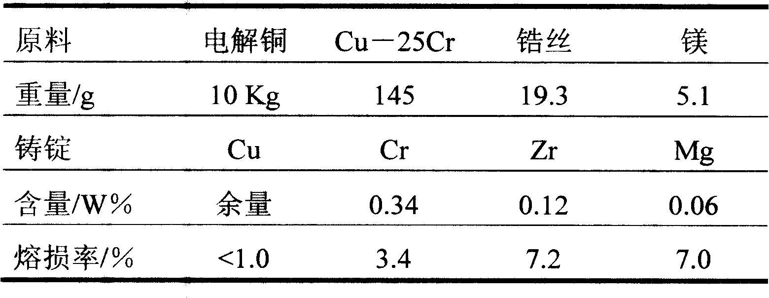
[0025] The present invention is carried out under the same conditions as in Example 1 by using zirconium wire instead of copper-clad zirconium. The chemical contents of raw materials and ingots are shown in Table 2. The loss rates of each metal during the smelting process are: Cu≤1.0%, Cr≤3.4% and Zr≤7.2%.

[0026] Table 2

[0027]

Embodiment 3

[0029] Adopt the same condition as embodiment 1, adopt N 2 In order to protect the gas, use a gas nozzle to extend into the melt from the feeding port 7 during the heat preservation process after smelting, and inject N 2 Pass into the melt for degassing. The chemical content of raw materials and ingots is shown in Table 3. According to the metallographic photos, it can be seen that the structure of the ingot is significantly improved, and the pores and inclusions are reduced. The loss rates of each metal during the smelting process are: Cu≤1.1%, Cr≤3.4% and Zr ≤7.1%.

[0030] table 3

[0031]


PUM


Abstract

The invention discloses a melting and casting Cu-Cr-Zr alloy method, which comprises the following steps: loading electrolytic copper, cupraloy and metal zirconium in the protective gas induction furnace; fusing; casting from bottom; connecting lower cast hole and crystallizer with gas protecting device. The whole course is protected by pure gas with low hydrogen and oxygen partial pressure, which provides good quality casting ingot.

Description

technical field [0001] The invention relates to the processing of Cu-Cr-Zr alloys, in particular to methods for smelting and casting Cu-Cr-Zr alloys, and belongs to the technical field of nonferrous metal processing. Background technique [0002] The traditional processing method of Cu-Cr-Zr alloy is to mix the electrolytic copper and other alloying elements in proportion and put them into the vacuum furnace. -3 The heating and smelting starts below the Pa, and the casting is directly carried out in a vacuum furnace after the smelting is completed. This smelting method, due to the high vacuum in the furnace, the gas partial pressure of oxygen is extremely low, which kinetically prevents the oxidation and burning of the smelted metals (Cu, Cr and Zr). During the smelting process, the copper melt contains a certain amount of oxygen and hydrogen, and a large chemical potential is generated between the inside of the melt and the smelting environment due to the concentration gra...

Claims


Application Information

Patent Timeline
Patent Type & Authority Patents(China)
IPC IPC(8): C22C1/03B22D21/00B22D9/00
Inventor 郭富安慕思国曹兴民向朝建杨春秀朱雯
Owner CHINA NON-FERROUS METALS PROCESSING TECH CO LTD
Learn More