Sludge drying system using combination of smoke residual heat and external heat supply source

A technology of flue gas waste heat and sludge drying, applied in the direction of dewatering/drying/concentrating sludge treatment, etc., can solve the problems of inability to meet the energy requirements of dried sludge, scattered and small amount, difficult to use, etc., and achieves remarkable results. Effects of social and environmental benefits

Inactive Publication Date: 2008-10-29
ZHEJIANG UNIV
View PDF11 Cites 1 Cited by
  • Summary
  • Abstract
  • Description
  • Claims
  • Application Information

AI Technical Summary

Problems solved by technology

[0004] According to our in-depth understanding, many places have more small-scale flue gas waste heat resources. Some of these flue gas waste heat resources come from the flue gas of small-power thermal power plants, and some come from flue gas discharged from various boilers. Because it is dispersed and the amount is small, it cannot meet the energy requirements for drying a certain amount of sludge, so it is difficult to be used

Method used


Image

  • Sludge drying system using combination of smoke residual heat and external heat supply source

Examples


Embodiment Construction

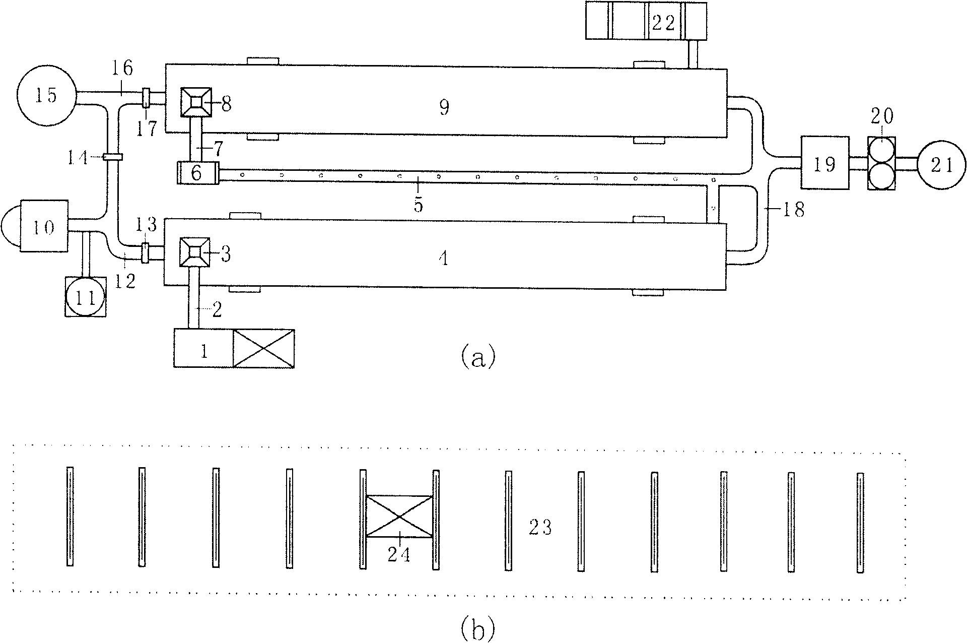
[0014] As shown in the attached figure, the sludge drying system combined with flue gas waste heat and external heat supply includes heating system, sludge pretreatment system, feeding system, sludge drying and granulation system, dust removal and gas removal, etc. subsystem.

[0015] The heating system has a fluidized fluidized furnace 10, a temperature regulator 11, a first ventilation pipe 12, a flue 16, a first damper 17, a second damper 13, a third damper 14, and a first induced draft fan 15. The heat energy provided by the fluidized fluidized furnace 10 is passed through The temperature regulator 11 controls the temperature at 200-400°C, the amount of hot air is controlled by the second air door 13, and sent to the first rotary drying kiln 4 through the first ventilation duct 12, and the amount of hot air is sent to the second rotary kiln 4 by the third air door 14. In the rotary drying kiln 9, the first induced draft fan 15 sends the flue gas passing through the dust co...


PUM

PropertyMeasurementUnit
diameteraaaaaaaaaa
diameteraaaaaaaaaa
diameteraaaaaaaaaa

Abstract

A sludge drying system with the combination of fume's afterheat and external heat source is composed of heat supply system, sludge pre-treating system, feeding system, sludge drying-granulating system and dusting and degassing system.

Description

technical field [0001] The invention relates to a sludge drying system which combines flue gas waste heat with an external heat supply source. Background technique [0002] Urban domestic sewage and industrial wastewater must be treated by sewage treatment plants, and can only be discharged after reaching the national sewage discharge standard, which has become a mandatory environmental protection engineering measure. On the one hand, the duty of urban sewage treatment plants is to purify sewage, so that urban domestic sewage and industrial wastewater can be discharged up to standard after treatment; on the other hand, it is to safely dispose of sludge generated during sewage treatment to prevent secondary environmental pollution caused by sludge . In recent decades, through the continuous introduction and digestion of foreign advanced technology, my country's water treatment technology has become increasingly mature, and all kinds of sewage can generally meet the discharge...

Claims


Application Information

Patent Timeline
Patent Type & Authority Patents(China)
IPC IPC(8): C02F11/12
Inventor 翁焕新
Owner ZHEJIANG UNIV
Why Eureka
Try Eureka