Zero-point micromachinery and microwave filter with dual-tuning transmission

A microwave filter, transmission zero technology, applied in waveguide-type devices, electrical components, circuits, etc., to achieve the effect of easy implementation, increased flexibility, and simple structure

Active Publication Date: 2009-06-10
NO 55 INST CHINA ELECTRONIC SCI & TECHNOLOGYGROUP CO LTD
View PDF4 Cites 0 Cited by
  • Summary
  • Abstract
  • Description
  • Claims
  • Application Information

AI Technical Summary

Problems solved by technology

However, microwave grounding technology is a difficult point in the manufacture of microwave integrated circuits, so it limits its development and becomes one of the bottlenecks in the development of micro-filters.

Method used


Image

  • Zero-point micromachinery and microwave filter with dual-tuning transmission
  • Zero-point micromachinery and microwave filter with dual-tuning transmission
  • Zero-point micromachinery and microwave filter with dual-tuning transmission

Examples


Embodiment Construction

[0026] The present invention will be further described below in conjunction with the accompanying drawings and embodiments.

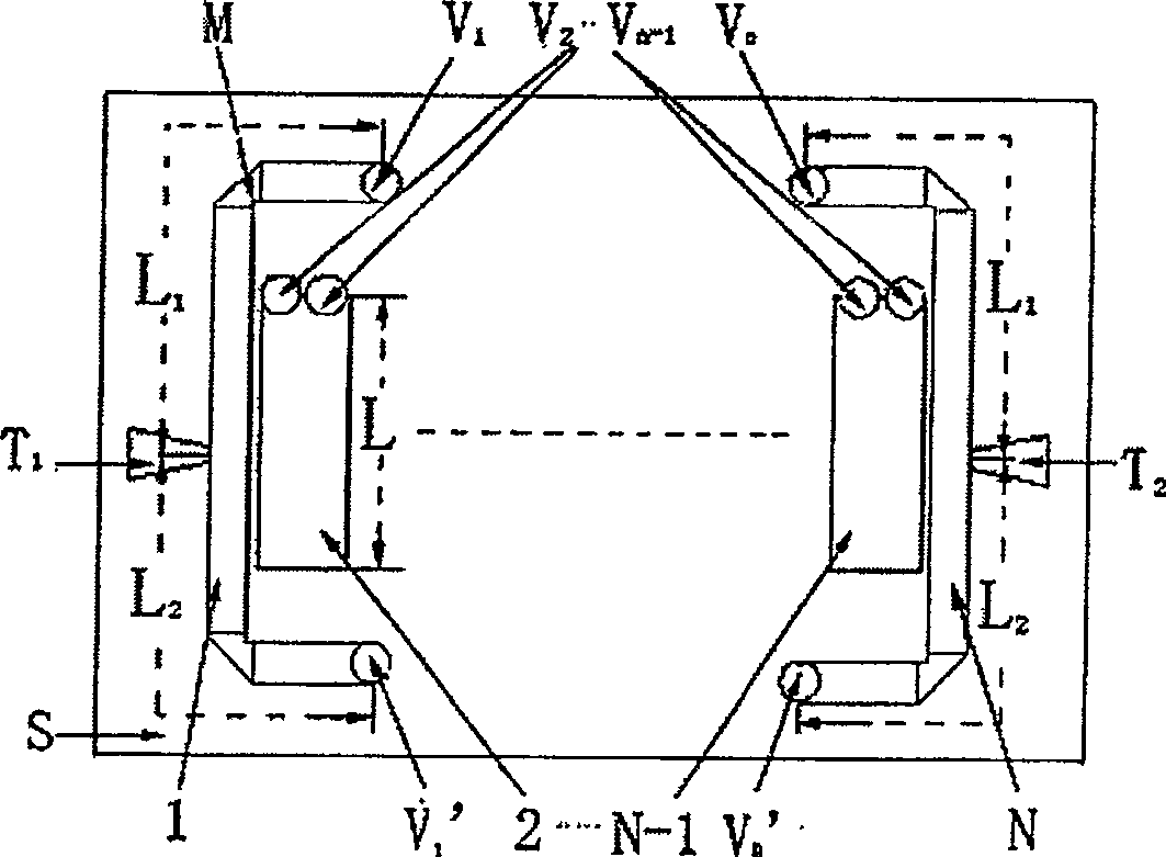
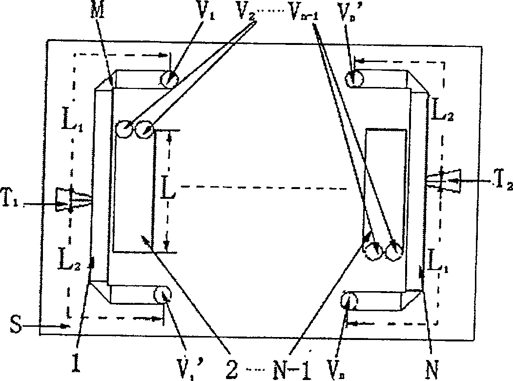
[0027] Such as figure 1 , 2 shown. figure 1 , 2 Middle: 1 is the first section of the microwave transmission line; 2~N-1 is the intermediate microwave coupling transmission line resonator; N is the last section of the microwave transmission line; T 1 is the tap line input; T 2 is the output end of the tap line; L is the length of the intermediate transmission line resonator; L 1 , L 2 is the distance between the connection of the tap line and the two ground ends of the transmission line; M is the matching corner of the transmission line. S is a substrate.

[0028] Wiper Line Input (T 1 ) is connected to the first section of microwave transmission line 1, the first section of microwave transmission line 1 is coupled to the intermediate coupling transmission line resonator 2, ..., N-1 is coupled until the last section of microwave transmission lin...


PUM


Abstract

The invention improves Techebyshev type microwave filter. Its basic structure adopts distributive coupling line structure. The length of (2)-(N-1) node micro wave transmission line in the middle is 1 / 4 wave length of designed frequency, and one end of the transmission line connects to ground via micro through-hole (V2-VN-1). The both end of two node in head and end(1),(N)micro wave transmission line connects to ground via micro through-hole (V1,V1'),(VN,VN'). The signal coupling adopts tapped line structure (T1, T2). The distance from (T1, T2) to(V1,V1'),(VN,VN')is L1,L2. By adjusting L1 and L2, implement two transmission zeros at appropriate frequency point and improve outband rejection property.

Description

technical field [0001] The invention belongs to the intersecting fields of microwave circuits, microelectronics and micro-electromechanical systems, and is used in microwave circuits to pass signals of required frequency bands with as little attenuation as possible, and attenuate signals of unnecessary frequency bands at the same time. In particular a filter of the generalized Chebyshev bandpass filter type, and in particular a double-tuned transmission-zero micromechanical microwave filter. Background technique [0002] Microwave filter design requires small size, small insertion loss, high out-of-band rejection, and good impedance matching characteristics. The types of microwave filters mainly include lumped element (inductor, capacitor) form, distributed transmission line type, ceramic, cavity type, etc. In satellite, communication, aviation, aerospace and other systems, electronic systems are required to be small in size, light in weight and low in cost. Today, with the...

Claims


Application Information

Patent Timeline
Patent Type & Authority Patents(China)
IPC IPC(8): H01P1/201H01P1/203H01P1/205H01P1/20
Inventor 朱健郁元卫张勇
Owner NO 55 INST CHINA ELECTRONIC SCI & TECHNOLOGYGROUP CO LTD
Why Eureka
Try Eureka