Optical detection device and working method for tissue of living body

A living tissue and optical detection technology, applied in medical science, diagnostic recording/measurement, diagnosis, etc., can solve problems such as inability to accurately detect tumor lesions in living tissue, lagging electrical signal control feedback, and inability to obtain diffuse reflectance spectra

Inactive Publication Date: 2009-07-01
马剑文 +3
View PDF14 Cites 0 Cited by
  • Summary
  • Abstract
  • Description
  • Claims
  • Application Information

AI Technical Summary

Problems solved by technology

The disadvantage of this technical solution is that this solution only considers the scattering characteristics of light on tissue cells, and does not consider the light absorption characteristics of chromophores in tissue bodies, which leads to low reliability of its measurement results and easily leads to missed or misdiagnosed
The disadvantage of this solution is that it mainly obtains the characteristics of the tissue by detecting the transmission spectrum, which is similar to X-ray breast detection. This method needs to compress the breast tissue to a certain extent before the detection can start, which brings certain pain to the patient. , and cannot detect and diagnose in vivo tissues
The disadvantage of this system is: when the computer in the system is working, it uses the light received by the monitor system to analyze the physical characteristics of the measured surface layer, and at the same time, the change of the light intensity is used as the feedback signal of the light source, and the light source is controlled by the controller. Output stability, this kind of feedback control is more complicated, and the electrical signal control often has a serious feedback lag, resulting in unstable output of the light source, which in turn leads to a large detection error of the system
In addition, the system cannot compare the light intensity of each wavelength output by the light source with the light intensity of the diffuse reflection light from the tissue surface, resulting in a large deviation in the diffuse reflection spectrum obtained by the computer that can be used to analyze the physical properties of biological tissues, and even cannot be used. diffuse reflectance spectrum, so the reliability of the system is not high
[0011] The disadvantage of the above prior art is that it can only optically detect the living tissue of a single depth, but the actual situation is that the living tissue of the disease has a certain horizontal area and longitudinal depth, and the living tissue of a single depth can only be detected by optical detection. Optical detection clearly cannot accurately detect the status of neoplastic lesions in living tissue

Method used


Image

  • Optical detection device and working method for tissue of living body
  • Optical detection device and working method for tissue of living body
  • Optical detection device and working method for tissue of living body

Examples


Embodiment 1

[0049] (Example 1. Optical detection device for living body tissue)

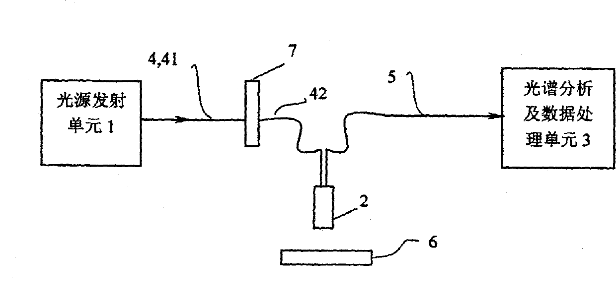
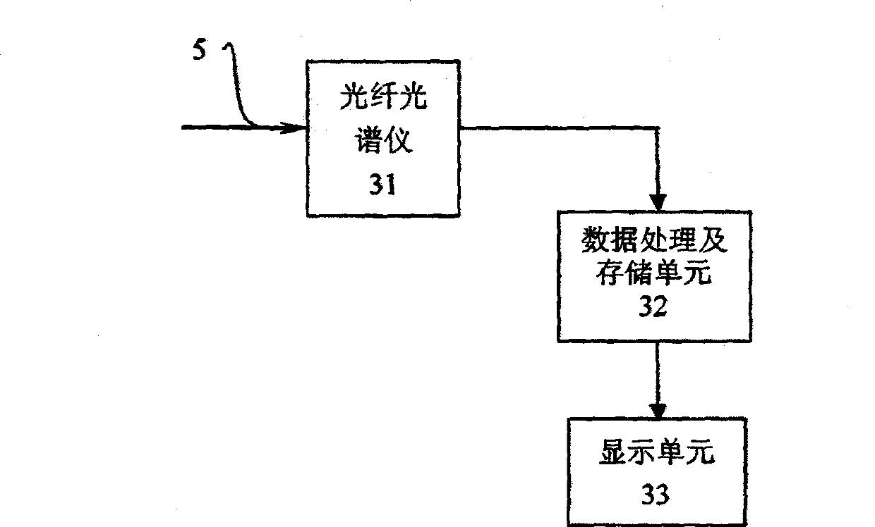
[0050] see figure 1 , The living body tissue optical detection device of this embodiment has a main detection device and a diffuse reflection plate 6 independent of the main detection device. The main detection device includes a main detection main device body; the main detection main device main body has a light source transmitting unit 1, an optical fiber probe 2, a spectrum analysis and data processing unit 3, a transmitting optical fiber 4, a receiving optical fiber 5, and an optical switch 7.

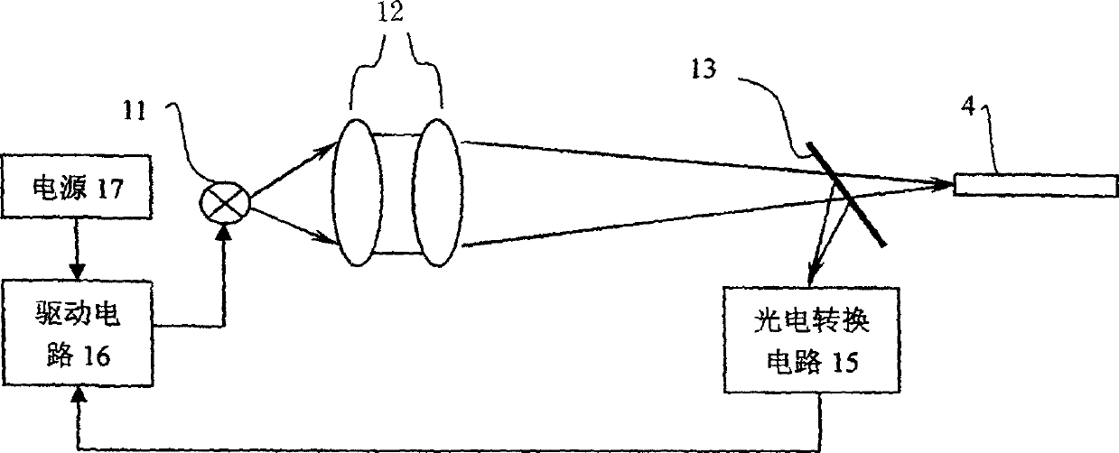
[0051] The light source emitting unit 1 is a device that emits light in the wavelength range of 400 to 1000 nanometers when in use (the light emitted in this embodiment has a continuous white light spectrum when used, and its wavelength bands are visible light and near-infrared wavelengths, and can also choose to emit continuous visible light. Light source emission unit 1, or alternatively select the light source em...

Embodiment 2

[0064] (Example 2. Optical detection device for living tissue)

[0065] see Figure 7 , Figure 4-2 with Figure 5-2 , The rest is the same as embodiment 1, the difference is: in this embodiment, the transmitting fiber 4 is changed to a single fiber, the receiving fiber 5 is divided into two sections, and the front section 51 of the receiving fiber 5 is a three-fiber Optical fiber bundle (in other embodiments, it can be any possible value greater than three, such as 6, 10, 20, etc., or two, and the number of branches at the branch end 72 of the corresponding optical switch 7 is not less than that of the optical fiber The number of the optical fiber 5), the rear section 52 of the receiving optical fiber 5 is a single optical fiber. The number of optical switches 7 is still 1.

[0066] see Figure 4-2 and Figure 5-2 In this embodiment, the front end of the transmitting optical fiber 4 is connected to the light source output end of the light source transmitting unit 1; the rear end ...

Embodiment 3

[0068] (Embodiment 3, optical detection device for living tissue)

[0069] see Figure 8 , Figure 4-3 and Figure 5-3 , The rest is the same as embodiment 1, the difference is: the receiving optical fiber 5 is divided into front and rear sections, the front section 51 of the receiving optical fiber 5 is an optical fiber bundle with two optical fibers, and the rear section 52 of the receiving optical fiber 5 is a single optical fiber . The number of optical switches 7 is 2, and the first optical switch 7 is arranged in series by its optical port between the rear end of the optical fiber in the front section 41 of the emission fiber 4 and the front end of each optical fiber in the rear section 42 of the emission fiber 4, The second optical switch 7 is arranged in series with its optical port between the rear end of each optical fiber in the front section 51 of the receiving optical fiber 5 and the front end of the optical fiber in the rear section 52 of the receiving optical fiber ...


PUM


Abstract

The invention relates to a living tissue detection device and a working method thereof. The detection device of the present invention includes a light source transmitting unit, an optical fiber probe, a spectrum analysis and data processing unit, a transmitting optical fiber, a receiving optical fiber and an optical switch; All or part of the distances between the root optical fiber and each optical fiber in the receiving optical fiber are different, and the number of these different distances is greater than or equal to two. The working method of the detection device of the present invention is: use the ratio sequence obtained by comparing the light intensity information of each wavelength in the diffuse reflection light of the living tissue obtained through detection with the light intensity reference to obtain the diffuse reflection spectrum signal, and control the optical switch. The state detects the states of different depths of the living tissue to obtain the detection results. The invention not only can perform tomographic optical detection, but also has high detection precision.

Description

Technical field [0001] The invention relates to a device for detecting living body tissues and a working method thereof. The results obtained through the detection can be used by medical staff for optical detection of tumors in living tissues, etc. Background technique [0002] Non-invasive detection of the human body, especially the tissues in the human body, has important significance in clinical medicine, especially the non-destructive and rapid diagnosis of various tumors, which is of great significance for early diagnosis and improving the survival rate of cancer patients. [0003] The diagnosis of cancer by doctors is mostly based on experience and the examination of biopsy. It is subjective and blind, which makes early lesions easy to be missed or misdiagnosed. [0004] Laser medicine is an emerging discipline of modern medicine. It integrates high and new technologies in the fields of laser, spectroscopy, fiber optics, optical information processing, and tissue optical pr...

Claims


Application Information

Patent Timeline
Patent Type & Authority Patents(China)
IPC IPC(8): A61B5/06A61B5/00
Inventor 马剑文王成徐安成马博平
Owner 马剑文
Why Eureka
Try Eureka