Flow for separating outflow from hydrogenation reaction

A hydrogenation reaction and effluent technology, applied in the direction of effluent separation, etc., can solve the problems of no heat recovery, low energy recovery and utilization rate, complex separation system, etc., and achieve high energy recovery and utilization rate, platform The effect of reduction and simple process

Active Publication Date: 2009-07-08
CNPC EASTCHINA DESIGN INST
View PDF4 Cites 4 Cited by
  • Summary
  • Abstract
  • Description
  • Claims
  • Application Information

AI Technical Summary

Problems solved by technology

The disadvantage of this separation process is that energy recovery and utilization are low
[0008] CN98112925.0, CN98112915.3, CN02114456.7, etc. disclose the separation method of hydrocarbon hydroconversion or hydrotreating process to generate oil, by using multiple gas-liquid separators, the liquid hydrocarbons in the separation system can be further absorbed and separated gaseous hydrocarbons in the system, increasing C 3 + Hydrocarbon recovery, but the separation system is complex and does not involve heat recovery

Method used


Image

  • Flow for separating outflow from hydrogenation reaction
  • Flow for separating outflow from hydrogenation reaction

Examples


Embodiment 1 and comparative example 1

[0029] Below through the embodiment a certain 150×10 4 The hydrogenation reaction effluent in the t / a hydrocracking process is compared with the present invention and the existing scheme to further illustrate the technical effect of the present invention.

Embodiment 1

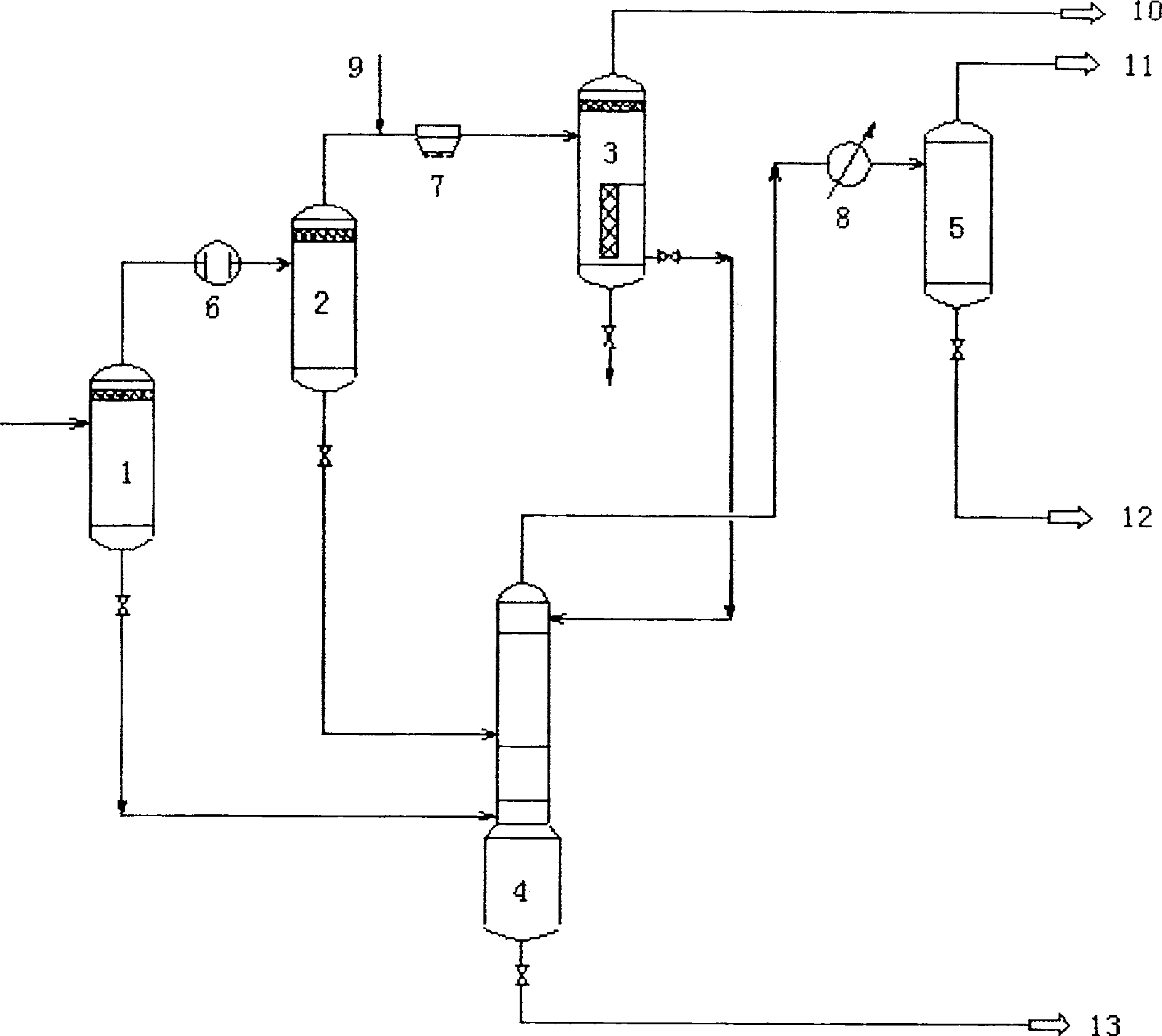
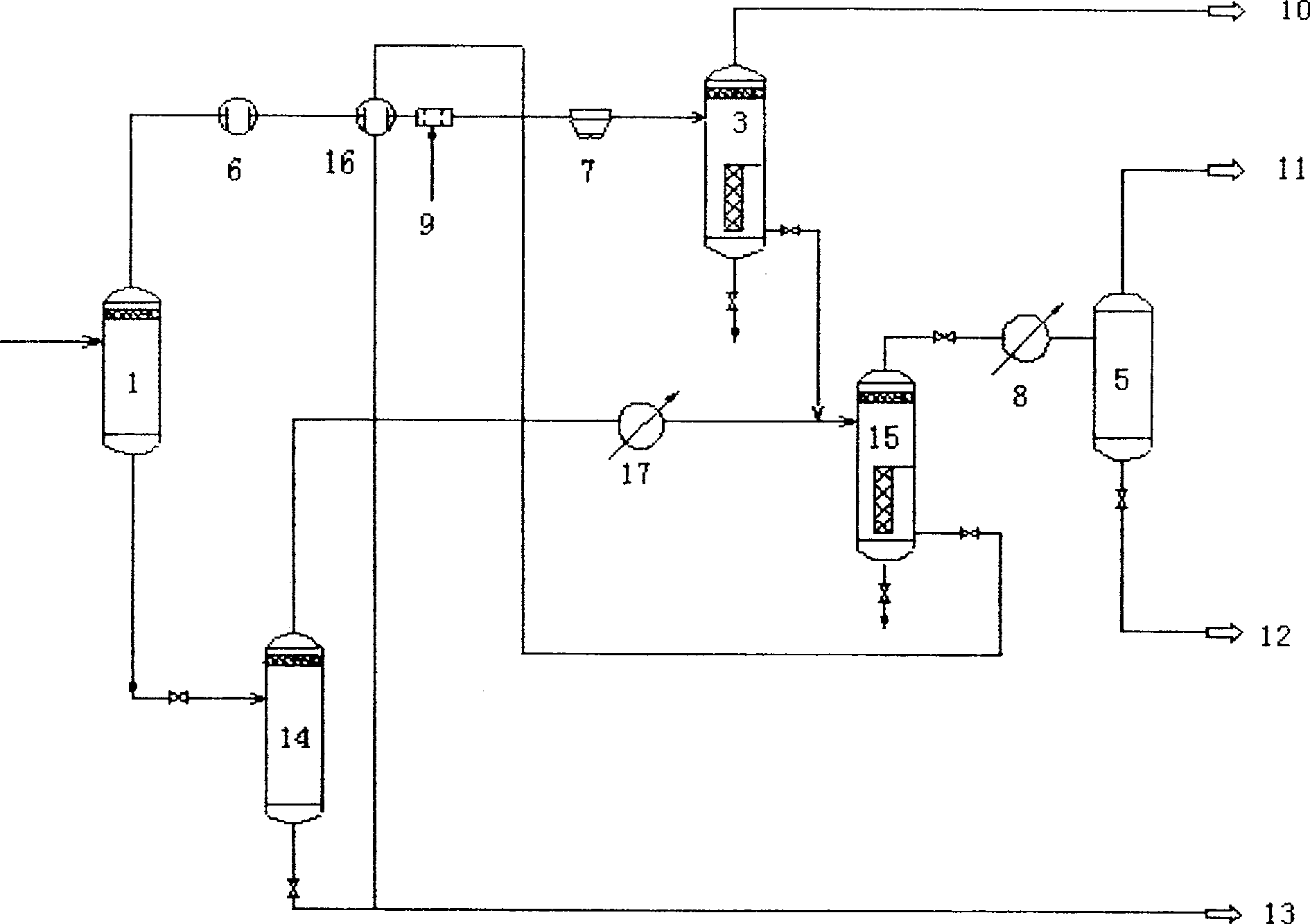
[0030] Embodiment 1 according to the process of the present invention ( figure 1 ) operation, comparative example 1 according to the existing process ( figure 2 )operate.

[0031] In Example 1 and Comparative Example 1, the temperature of the hydrocracking reaction effluent after preliminary heat exchange is 288° C., the pressure is 16.3 MPa, the flow rate is 335,830 kg / h, and the enthalpy value is 101,970 KW.

[0032] In embodiment 1, the operating temperature of the hot high-pressure separator 1 is 288°C, the heat load of the heat exchanger A6 is 22612KW, the operating temperature of the medium-temperature high-pressure separator 2 is 166°C, and the heat load of the air cooler 7 is 17719KW (unavailable heat), the operating temperature of the cold high-pressure separator 3 is 49°C. The heat exchange tower 4 adopts 15 theoretical trays, and the feed ports of the three kinds of streams are respectively arranged at the top, the middle (the 9th theoretical plate) and the botto...

Embodiment 2 and comparative example 2

[0051] Below through the embodiment a certain 150×10 4 The hydrogenation reaction effluent in the t / a coking whole distillate oil hydro-upgrading process is compared with the present invention and the existing scheme (the calculation result of the process simulation software PRO II), further illustrating the technical effect of the present invention.


PUM


Abstract

The invention relates to a hydrogenation reaction effluent separation process, comprising (1) the hydrogenation reaction effluent enters a hot high-pressure separator, (2) the gas phase separated from the hot high-pressure separator enters a medium-temperature high-pressure separator after cooling down, (3) The gas phase separated by the medium-temperature high-pressure separator cools down and enters the cold high-pressure separator, and the gas phase separated by the cold high-pressure separator is used as circulating hydrogen. (4) A heat exchange tower is installed, and the liquid phase of the hot high-pressure separator enters the heat exchange tower from the lower part. The liquid phase of the high-pressure separator enters the heat exchange tower from the middle, the liquid phase of the cold high-pressure separator enters the heat exchange tower from the top, the liquid phase is drawn out from the bottom of the heat exchange tower for stripping treatment, and the gas phase discharged from the top of the heat exchange tower enters the gas phase after being cooled. Liquid separator for separation. Compared with the prior art, the method of the invention has simple process flow, fewer high-pressure equipment stations, significantly reduced heat exchange area of ​​heat exchange equipment, reduced cooling load and high energy recovery and utilization rate. The method of the invention is applicable to various hydrogenation reaction processes utilizing heat separation.

Description

technical field [0001] The invention relates to a thermal separation process of hydrogenation reaction effluent, that is, a separation method of reaction effluent in hydrogenation process using heat separation, especially a separation method of reaction effluent in hydrocracking process. Background technique [0002] The quality of crude oil in the world is getting worse and worse, and the properties of products obtained from crude oil processing are also getting worse; and with the increasingly stringent environmental protection regulations, the quality requirements for various petroleum products are gradually increasing. Hydrogenation process is an important processing method to provide high-quality petroleum products, so it has been highly valued, the application range is more and more extensive, and the processing capacity is increasing year by year. According to the different properties of raw materials and product requirements, different types of hydrogenation processe...

Claims


Application Information

Patent Timeline
Patent Type & Authority Patents(China)
IPC IPC(8): C10G49/22
Inventor 王德会辛若凯王国旗李利民李胜山
Owner CNPC EASTCHINA DESIGN INST
Why Eureka
Try Eureka