Improvements relating to electrode structures in batteries

A technology of electrode structure and electrode composition, applied in battery electrodes, non-aqueous electrolyte battery electrodes, electrode manufacturing, etc., can solve the problems of reduced porosity, increased energy density of chemical sources, and reduced ion conductivity of electrodes

Active Publication Date: 2007-07-18
JOHNSON MATTHEY PLC
View PDF7 Cites 63 Cited by
  • Summary
  • Abstract
  • Description
  • Claims
  • Application Information

AI Technical Summary

Problems solved by technology

[0019] On the one hand, an increase in electrode density (reduced porosity) leads to an increase in the energy density of the chemical source of electrical energy
On the other hand, the reduced porosity leads to a decrease in the ionic conductivity of the electrode, which in turn makes the electrochemical reaction conditions and the utilization of active materials worse.

Method used


Image

  • Improvements relating to electrode structures in batteries

Examples


Embodiment 1

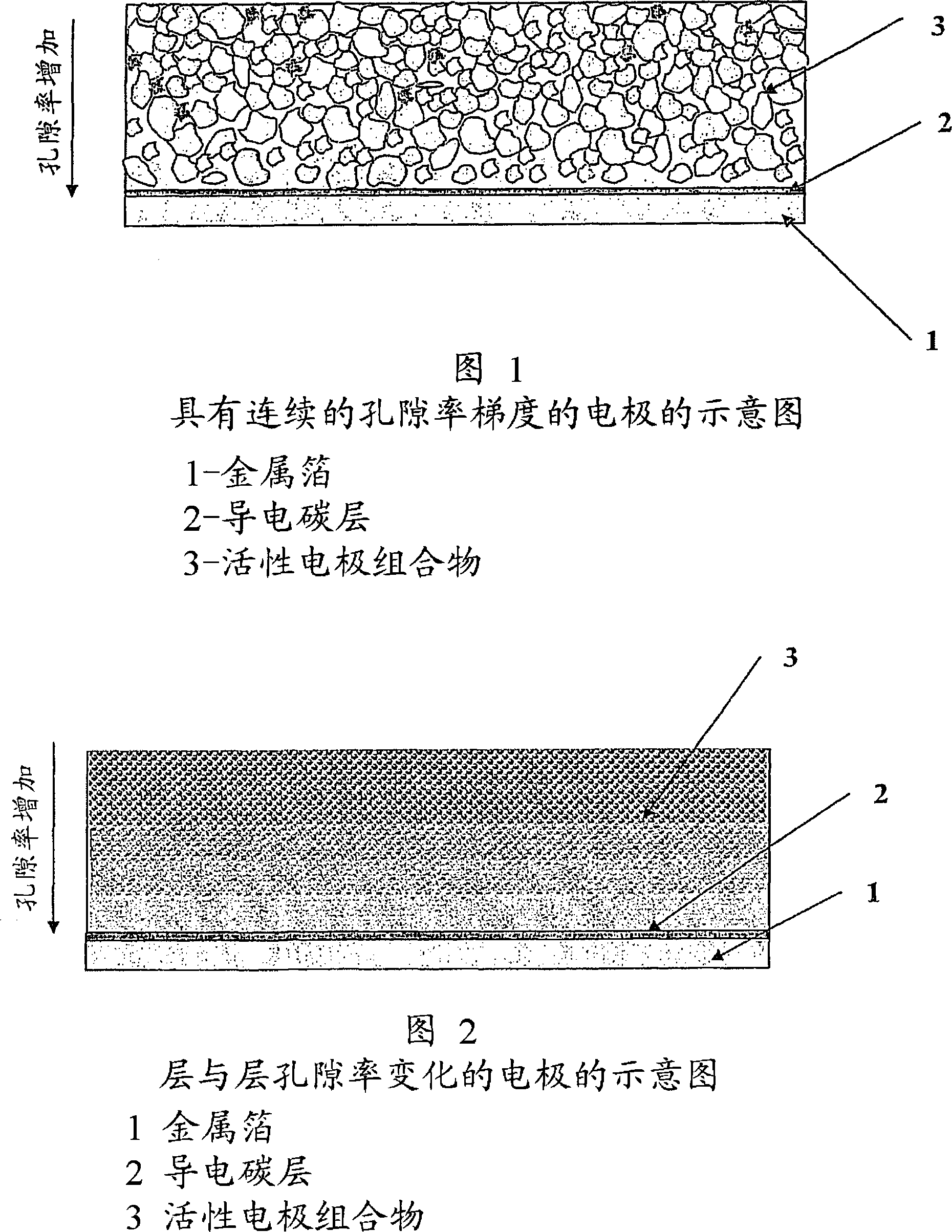
[0077] A cathode active layer having a composition consisting of 70% by weight elemental sulfur (available from Fisher Scientific, Loughborough, UK), 10% by weight conductive carbon black (Ketjenblack(R) EC) was prepared by the following method. -600JD, available from Akzo Nobel Polymer Chemicals BV, The Netherlands) and 20% by weight polyethylene oxide (PEO, 4,000,000 molecular weight, available from Sigma-Aldrich Ltd, Greenham, UK). The mixture of dry ingredients was milled for 10-15 minutes in a Microtron(R) MB550 homogenizing system. Acetonitrile was added as a solvent to the obtained mixture. The finally obtained liquid suspension or slurry was mixed for 15-20 hours using a laboratory mixer DLH. The solid matter in the slurry accounts for 10%-15% by weight. Using an Elcometer(R) SPRL automatic film applicator with a squeegee, the resulting mixture was coated onto an aluminum foil coated with 18 micron thick conductive carbon (available from South Harbour, Massachusetts,...

Embodiment 2

[0080] The slurry from Example 1 was applied by an Elcometer(R) SPRL automatic film applicator with a squeegee onto an aluminum foil coated with 18 micron thick conductive carbon (available from Massachusetts, USA) as current collector and substrate. InteliCoat(R) in South Hadley). The gap of the squeegee is different from that of the squeegee used in Example 1. The above coating was dried at ambient conditions for 20 hours and then dried under vacuum at 50° C. for 5 hours.

[0081] The finally obtained dry cathode active layer has a thickness of about 21 microns, loaded with 1.35 mg / cm 2 cathode composition. The bulk density of the electroactive coating is about 636 mg / cm 3 . The porosity of the cathode active layer was 65%.

Embodiment 3

[0083] A second layer of slurry was applied on top of the solid composite cathode from Example 1 by an Elcometer(R) SPRL automatic film applicator. The new coating was dried at ambient conditions for 20 hours and then dried under vacuum at 50°C for an additional 5 hours.

[0084] The finally obtained dry cathode active layer has a total thickness of about 25 microns, loaded with 2.23 mg / cm 2 cathode composition. The bulk density of the two-layer electroactive coating is about 890 mg / cm 3 . The porosity of the cathode active layer was 55%.


PUM

PropertyMeasurementUnit
thicknessaaaaaaaaaa
densityaaaaaaaaaa
densityaaaaaaaaaa

Abstract

There are disclosed solid composite electrodes with electrode active layers that include an electrode active material, an optional electron conductive material, an optional binder and other optional additives. The solid composite electrodes are formed by the deposition of an electrode composition (slurry) onto a current collector in one or many layers. The electrode structure is characterised by a porosity of the electrode composition layer that decreases in a direction from the back side of the layer (close to the current collector) towards the outer side of the layer. The gradient of the decrease in the porosity is controlled by the content of solid substance in the slurry, by the composition of the solvent in the slurry, by the temperature of the layer drying after deposition, as well as by the pressing or calendering conditions for each layer. The electrode structures can be used in chemical sources of electric energy such as primary (non-rechargeable) as well as secondary (rechargeable) batteries.

Description

technical field [0001] The present invention relates to a chemical source of electrical energy comprising a positive pole (cathode) and a negative pole (anode). In particular, the invention relates to rechargeable (secondary) and non-rechargeable (primary) batteries comprising a negative electrode (anode) providing ions, an intermediate separator element (separator element) and an electrode depolarizing substance (cathode). positive electrode (cathode) of the active material), where the separated component in the middle contains an electrolyte solution or a hard polymer electrolyte, and during charge and discharge cycles of the battery, ions start from the source electrode material and pass through the electrolyte solution or hard polymer electrolyte electrolyte and move between the electrodes of the battery. One or both of the positive and negative electrodes are coated with a porous electrochemically active material. The present invention is particularly useful for making ...

Claims


Application Information

Patent Timeline
Patent Type & Authority Applications(China)
IPC IPC(8): H01M4/04H01M4/58H01M4/02H01M4/13H01M4/131H01M4/133H01M4/136H01M4/139H01M4/1391H01M4/1393H01M4/1397H01M4/36H01M4/38H01M4/50H01M4/505H01M4/60H01M4/62H01M10/0525H01M10/0565H01M10/36
CPCH01M4/505H01M4/133H01M4/136H01M4/131H01M10/0565H01M10/0525H01M4/382H01M4/1391H01M4/0435H01M4/38H01M4/581H01M4/623H01M4/602H01M4/1393H01M4/1397Y02E60/122H01M4/625H01M4/5815H01M4/0404H01M4/626H01M4/139H01M4/13H01M2004/021H01M4/366Y02E60/10Y02P70/50H01M4/80H01M4/04H01M4/36H01M4/58
Inventor 弗拉迪米尔·克洛什尼特斯叶连娜·卡拉塞夫
Owner JOHNSON MATTHEY PLC
Why Eureka
Try Eureka