
Method for deacidizing low sulfur dioxide concentration by using gas produced by biomass pyrolysis

A sulfur dioxide, low-concentration technology, applied in the field of flue gas desulfurization, can solve problems such as energy waste, environmental pollution, and the safety of waste residue utilization to be investigated, and achieve the effect of reducing emissions and broad application prospects

Inactive Publication Date: 2007-09-19
KUNMING UNIV OF SCI & TECH
View PDF2 Cites 14 Cited by
  • Summary
  • Abstract
  • Description
  • Claims
  • Application Information

AI Technical Summary

Problems solved by technology

In the process of making the desulfurizer, too many chemical substances are added, which increases the cost and complexity, and the safety of the waste residue utilization remains to be investigated.
[0006] Renewable energy is the follow-up energy technology theme set by the country in the "Tenth Five-Year" 863 plan. my country is a country rich in biomass energy. There are about 700 million tons of crop straw, rice husk and forestry waste every year, of which about 80% are Crop stalks are incinerated by direct combustion, which causes a huge waste of energy and pollutes our environment

Method used


Image

  • Method for deacidizing low sulfur dioxide concentration by using gas produced by biomass pyrolysis

Examples


Embodiment 1

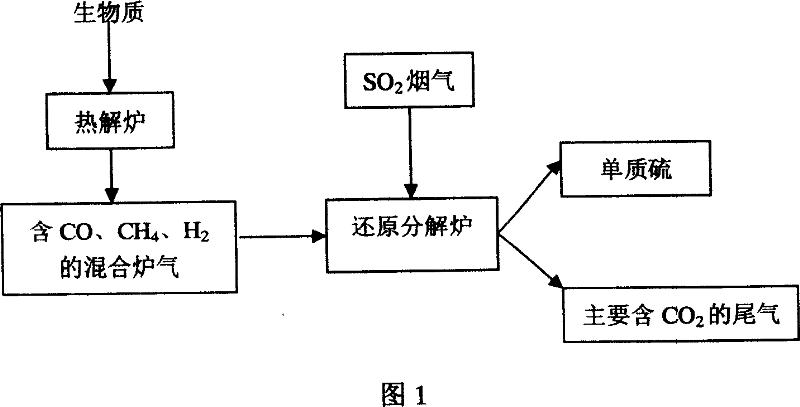
[0026] Embodiment 1: TiO 2 The carrier is immersed in 15% ferric nitrate solution for 4 hours, dried at 110-120°C until the water content is below 2wt%, and then calcined at 500-600°C for 4.5-5 hours until ferric nitrate is decomposed to form iron oxide, and finally mixed with gas ( SO 2 :N 2 =1:9) after pre-curing for 2 hours. The prepared catalyst is loaded into the reduction and decomposition furnace to make a catalytic reduction fixed bed; the raw material of the desulfurizer is stalk, and the stalk with a water content of 10% after drying is crushed to a particle size below 20mm, and the crushed stalk enters The pyrolysis reaction is carried out in the pyrolysis furnace, the temperature is controlled at 450 ° C ~ 550 ° C, and the reaction is carried out for 1 hour. During the reaction, the CO and CH in the furnace gas are continuously detected online by a flue gas analyzer. 4 、H 2 Concentration, the generation mainly contains 30% CO, 30% CH 4 , 20%H 2 The mixed pyro...

Embodiment 2

[0027] Example 2: the gamma-Al 2 o 3 The carrier was immersed in a 5% lanthanum nitrate solution for 6 hours, dried at 110-120°C to a moisture content of 0.5wt%, and then calcined at 600°C for 4 hours until the lanthanum nitrate was decomposed to form lanthanum oxide, and finally mixed gas (SO 2 :N 2 =1:9) after pre-curing for 1.5h. The prepared catalyst is loaded into the reduction and decomposition furnace; the raw material of the desulfurizer is wood chips, and the wood chips with a water content of 15% after drying are crushed to a particle size below 3mm, and the crushed wood chips enter the pyrolysis furnace, and the temperature is controlled at 500℃~600℃, the biomass is pyrolyzed in the pyrolysis furnace for 1 hour, and the CO and CH in the furnace gas are continuously detected online by the flue gas analyzer during the reaction process 4 、H 2 concentration. Generate mainly 20% CO, 40% CH 4 , 10%H 2 Mixed furnace gas; pyrolysis reaction containing 20% ​​CO, 40% C...


PUM

PropertyMeasurementUnit
Particle sizeaaaaaaaaaa

Abstract

The invention relates to a process for reducing SO2 to elemental sulfur in flue gas by using biomass pyrolysis gas, which belongs to the desulfurization technic field. The pyrolysis reaction for the biomass is carried out in a pyrolysis oven to generate a mixed pyrolysis gas used as desulfurizer which mainly comprises CO, CH4, and H2, the prepared catalyst is filled in a reductive decomposition oven, the mixed pyrolysis gas and the flue gas containing low-concentration SO2 are introduced into the reductive decomposition oven to have a reduction reaction at temperature of between 600DEG C and1000DEG C for 1h to 3h, the volume percentage of the SO2 gas from reductive decomposition oven can be up to 0.006% to 0.65%, and the desulfurization percent can be up to 80% to 98%, thereby realizing waste reutilization.

Description

(1) Technical field [0001] The invention relates to a method for reducing sulfur dioxide gas in flue gas to elemental sulfur by utilizing biomass pyrolysis gas, and belongs to the technical field of flue gas desulfurization. (2) Background technology [0002] high concentration SO 2 Flue gas can be used to recover sulfur resources by contact catalytic acid production. At present, this method is basically adopted in my country's smelting industry. However, low concentration SO 2 Flue gas desulfurization technology is still in its infancy. my country's thermal power plant boiler flue gas and industrial boilers and industrial kilns in the iron and steel, non-ferrous metals, building materials and other departments mainly emit this kind of flue gas. SO in this kind of flue gas 2 The concentration is low (<3%). If the known desulfurization and acid production method is used, it will be very difficult technically and economically. In addition, the traditional flue gas desulf...

Claims


Application Information

Patent Timeline
IPC IPC(8): B01D53/76C10J3/68C10J1/207
Inventor 宁平寸文娟马林转何屏杨月红
Owner KUNMING UNIV OF SCI & TECH
Learn More