

Method for treating percolation liquid of water deficiency area garbage embedding field
A landfill and treatment method technology, which is applied in the field of high-concentration sewage treatment, can solve the problems of poor treatment effect, complicated methods, and high cost, and achieve the effects of lower infrastructure investment and operating costs, pollution control, and accelerated decomposition
- Summary
- Abstract
- Description
- Claims
- Application Information
AI Technical Summary
Problems solved by technology
Method used
Image

Examples
Embodiment 1
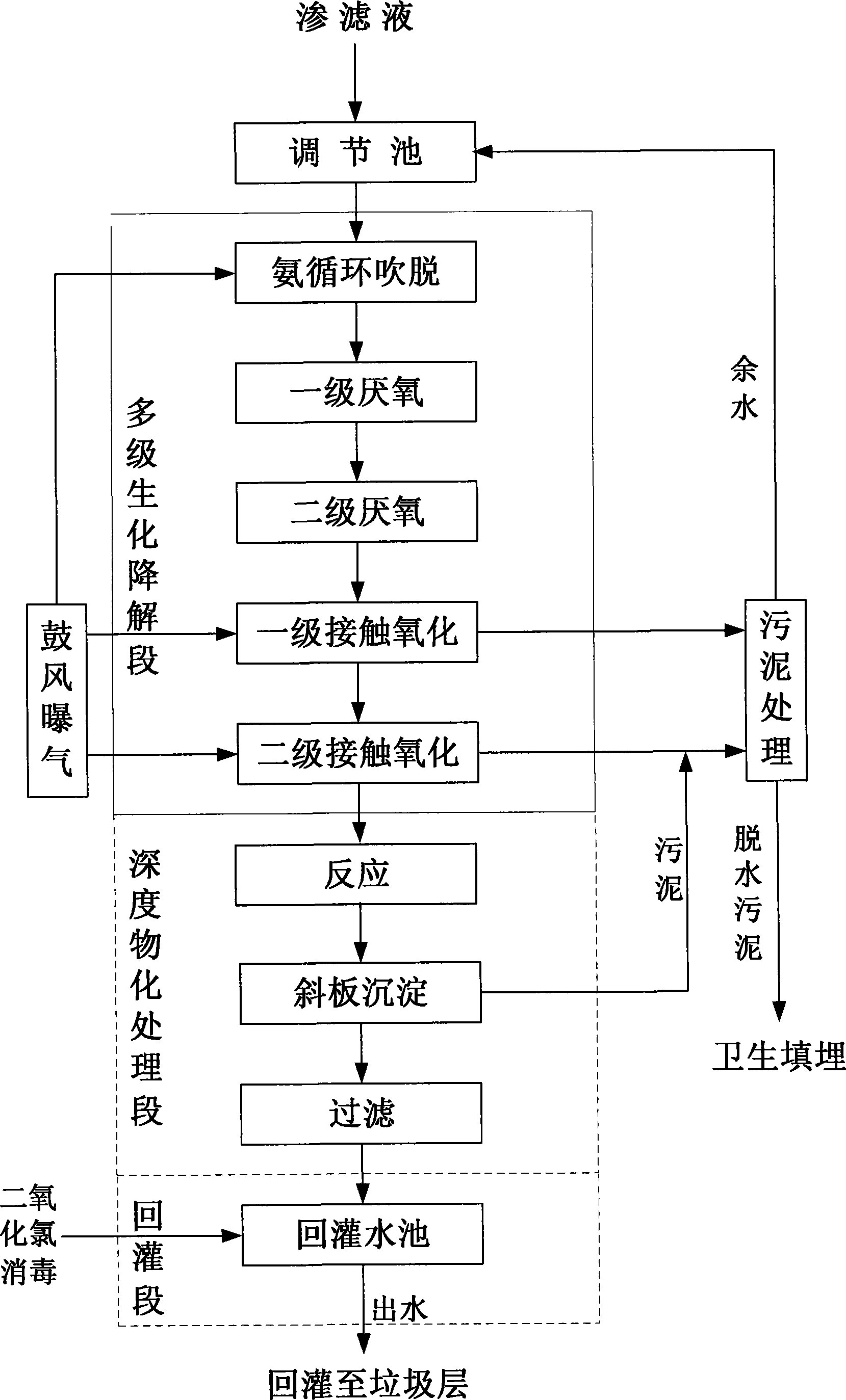
[0033] 1. Set up a regulating pool: set up a hydraulic regulating pool with a hydraulic retention time of 10 days.
[0034] Its function is to adjust the water quality and water quantity of the landfill leachate that changes drastically, and alleviate the impact on the subsequent treatment process. In addition to alleviating and adjusting the impact load, it can also play a role in initial settlement, and further protect the good operation of the overall treatment facility.
[0035] 2. Ammonia blow-off: The ammonia nitrogen with high content in landfill leachate is treated by circulating aeration ammonia blow-off tank. The hydraulic circulation ratio is 4:1, the gas-water ratio is 500:1, and the stripping time is 0.5h. The blow-off tank adopts the gas-water upflow type, and the water inlet and blowing gas flow upward through the packing layer from the lower part of the tank body. The middle part of the tank is a packing layer, which is filled with high mass transfer ceramsit...
Embodiment 2
[0052] 1. Set up the adjustment pool: the hydraulic adjustment pool is an underground reinforced concrete structure with a hydraulic retention time of 18 days.
[0053] 2. Ammonia blow-off: The ammonia nitrogen with high content in landfill leachate is treated by circulating aeration ammonia blow-off tank. The circulation ratio is 5:1, the gas-water ratio is 700:1, and the stripping time is 45 minutes. The blow-off tank adopts the gas-water upflow type, and the water inlet and blowing gas flow upward through the packing layer from the lower part of the tank body. The middle part of the tank is a packing layer, which is filled with high mass transfer ceramsite packing with a particle size of 4-6mm.
[0054] 3. Anaerobic treatment: the anaerobic process of the present invention adopts a two-stage upflow anaerobic sludge reactor (UASB).
[0055] The total hydraulic retention time of the two-stage anaerobic stage is 60h, and the ratio of the primary and secondary retention time ...
Embodiment 3
[0065] 1. Set up the adjustment pool: the hydraulic adjustment pool is an underground reinforced concrete structure, and the hydraulic retention time is 20d.
[0066] 2. Ammonia blow-off: The ammonia nitrogen with high content in landfill leachate is treated by circulating aeration ammonia blow-off tank. The circulation ratio is 5:1, the gas-water ratio is 900:1, and the stripping time is 1h. The blow-off tank adopts the gas-water upflow type, and the water inlet and blowing gas flow upward through the packing layer from the lower part of the tank body. The middle part of the tank is a packing layer, which is filled with high mass transfer ceramsite packing with a particle size of 4-6mm.
[0067] 3. Anaerobic treatment: the anaerobic process of the present invention adopts a two-stage upflow anaerobic sludge reactor (UASB).
[0068] The total hydraulic retention time of the two-stage anaerobic stage is 60h, and the ratio of the primary and secondary retention time is 2:3, th...
PUM
| Property | Measurement | Unit |
|---|---|---|
| Particle size | aaaaa | aaaaa |
Abstract
Description
Claims
Application Information