Process for producing molten iron and apparatus therefor

A manufacturing method and molten iron technology, applied in the field of molten iron manufacturing, can solve problems such as being unable to remain intact, and achieve the effects of prolonging life, high metallization, and reliable protection

Inactive Publication Date: 2007-10-03
KOBE STEEL LTD
View PDF2 Cites 9 Cited by
  • Summary
  • Abstract
  • Description
  • Claims
  • Application Information

AI Technical Summary

Problems solved by technology

[0005] However, the above process does not include a melting furnace and only produces metallic iron using a rotary hearth furnace, and the physical and chemical properties required for the bottom carbonaceous material, the recycling conditions of the bottom carbonaceous material, etc. cannot be used intact in combination therein Molten Iron Manufacturing Process Disclosed in Previous Prior Art Documents for Rotary Hearth Furnaces and Melting Furnaces

Method used


Image

  • Process for producing molten iron and apparatus therefor
  • Process for producing molten iron and apparatus therefor
  • Process for producing molten iron and apparatus therefor

Examples


no. 1 approach

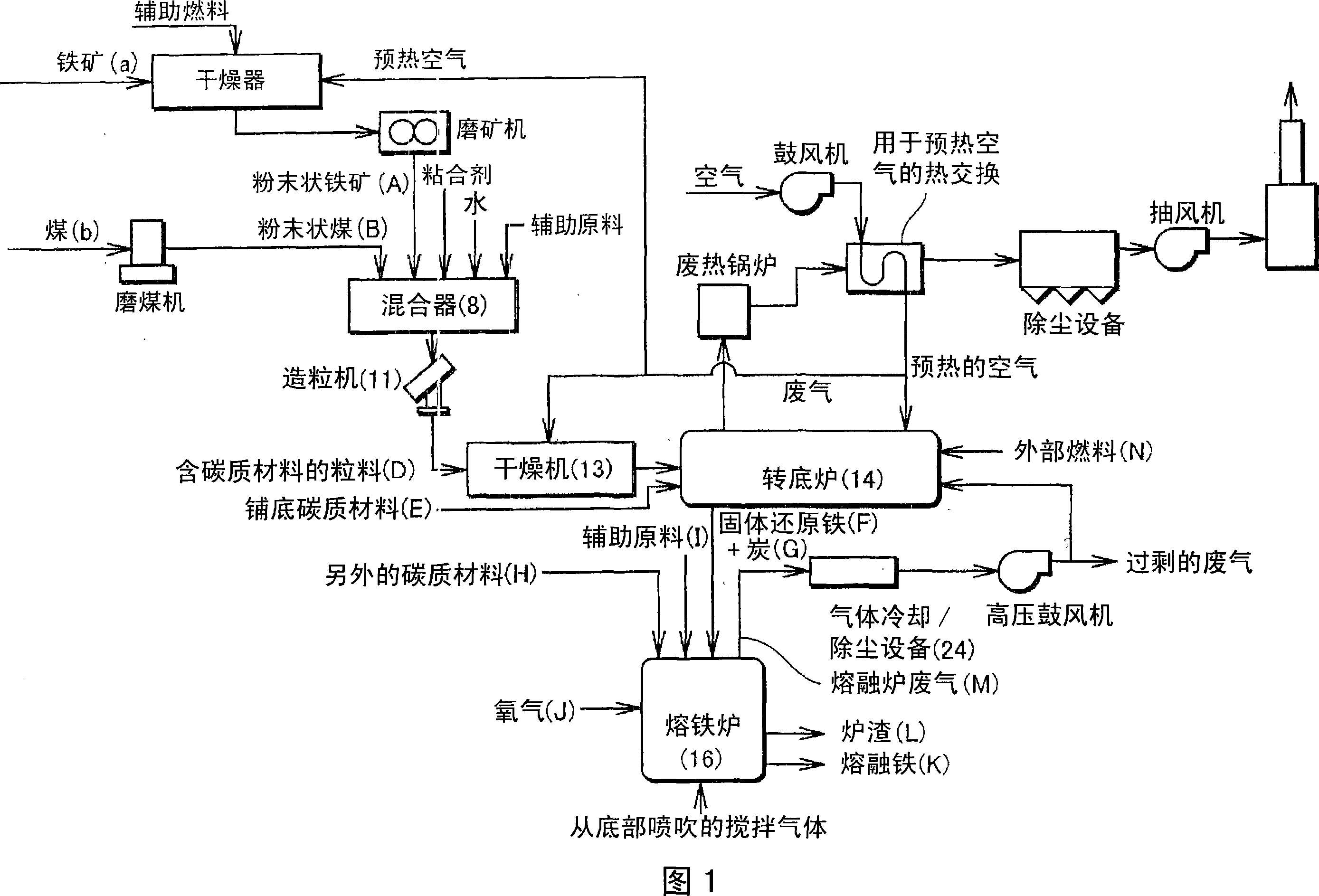
[0026] FIG. 1 is a flowchart showing a molten iron manufacturing process of one embodiment of the present invention, which is constructed by combining a rotary hearth furnace 14 and an iron melting furnace 16 as a live-bottom type reduction furnace.

[0027] When necessary, iron ore "a" as an iron oxide source and coal as a carbonaceous reducing agent are respectively pulverized into particles having a diameter of about less than 1 mm. The thus obtained powdered iron ore A as a source of powdered iron oxide and powdered coal B as a powdered carbonaceous reducing agent are mixed in a specified ratio, adding an appropriate amount of a binder and / or an appropriate amount of (In addition, all or part of the auxiliary raw material I can be added here, and the auxiliary raw material I is added to the iron melting furnace 16 as a slagging agent), and these are mixed by the mixer 8. After that, the mixed compound was granulated in the granulator 11 to have a particle diameter of about...

no. 2 approach

[0068] The following step (6) may be provided between the reduction step (the above step (2)) and the melting furnace charging step (the above step (3)).

[0069] (6) Step of thermoforming solid reduced iron F and char G together while they are hot

[0070] Specifically, solid reduced iron F and char G can be distributed together from, for example, a hopper 106 while hot, and press-formed into hot briquetted iron (HBI) by a thermoforming machine, and this HBI can be made Without cooling, it is dropped at a temperature of, for example, 500 to 1100° C. and charged into the melting furnace 16 .

[0071] This prevents fine particles from being scattered when charging into the iron melting furnace 16 and can significantly reduce the amount of dust in the exhaust gas from the iron melting furnace 16 . Therefore, iron yield and carbon yield can be significantly improved.

[0072] Since the purpose of shaping here is to eliminate fine particles, the shape of the compact is not limit...

no. 3 approach

[0074] The following steps (7) to (9) may be provided instead of the melting furnace charging step (the above-mentioned step (3)).

[0075] (7) After the solid reduced iron F and the char G are taken out together from the rotary hearth furnace 14, while they are hot or substantially without cooling, the solid reduced iron F and the char G are classified into coarse particles and thermal classification steps for fine particles;

[0076] (8) Utilize the coarse particle charging step that coarse particle is loaded in the melting iron furnace 16 by gravity;

[0077] (9) A fine particle spraying step of charging fine particles into the iron melting furnace 16 by spraying.

[0078] Specifically, devices having the following configurations can be used. A sieve having a mesh of about 2 to 5 mm is installed at the portion of the rotary hearth furnace 14 that discharges the solid reduced iron F and char G, and the solid reduced iron F and char G are screened while hot, wherein the coa...


PUM

PropertyMeasurementUnit
thicknessaaaaaaaaaa
diameteraaaaaaaaaa
thicknessaaaaaaaaaa

Abstract

Bedding carbon material (H) is charged onto the hearth of rotary hearth furnace (14), and carbon-material-incorporated pellets (D) containing powdery iron ore (A) and powdery coal (B) are placed on the bedding carbon material (H). The hearth is caused to pass through the inside of the rotary hearth furnace (14) to thereby attain not only heating reduction of the carbon-material-incorporated pellets (D) into solid reduced iron (F) but also heating dry distillation of the bedding carbon material (H) into char (G). Subsequently, these solid reduced iron (F) and char (G) substantially without cooling are charged into iron bath type melting furnace (16), and simultaneously oxygen gas is blown thereinto. The solid reduced iron (F) is melted, thereby obtaining molten iron (K). At least part of wastegas (M) from the iron bath type melting furnace (16) is subjected to cooling and dust removal and thereafter used as a fuel gas for the rotary hearth furnace (14).

Description

technical field [0001] The present invention relates to methods and apparatus for producing molten iron, and in particular to the efficient production of iron having a high Improved method of pure molten iron, said molten iron manufacturing process is constructed by combining a live-bottom type reduction furnace and a melting furnace. Background technique [0002] The inventors of the present invention studied a molten iron manufacturing method used in a molten iron manufacturing process in which a rotary hearth furnace (live bottom type reduction furnace) and a melting furnace (iron melting furnace) are combined, by the following steps Obtaining molten iron: After the briquettes containing iron oxide and carbonaceous reducing agent are heated in a rotary hearth furnace and reduced to solid reduced iron with a metallization degree equal to or higher than 60%, the solid reduced iron is conveyed to a melting furnace , and melting the solid reduced iron...

Claims


Application Information

Patent Timeline
Patent Type & Authority Applications(China)
IPC IPC(8): C21B11/00C22B1/16C21B13/10
Inventor 田中英年三村毅原田孝夫羽鹿公则八十格仓卦敏之
Owner KOBE STEEL LTD
Why Eureka
Try Eureka