

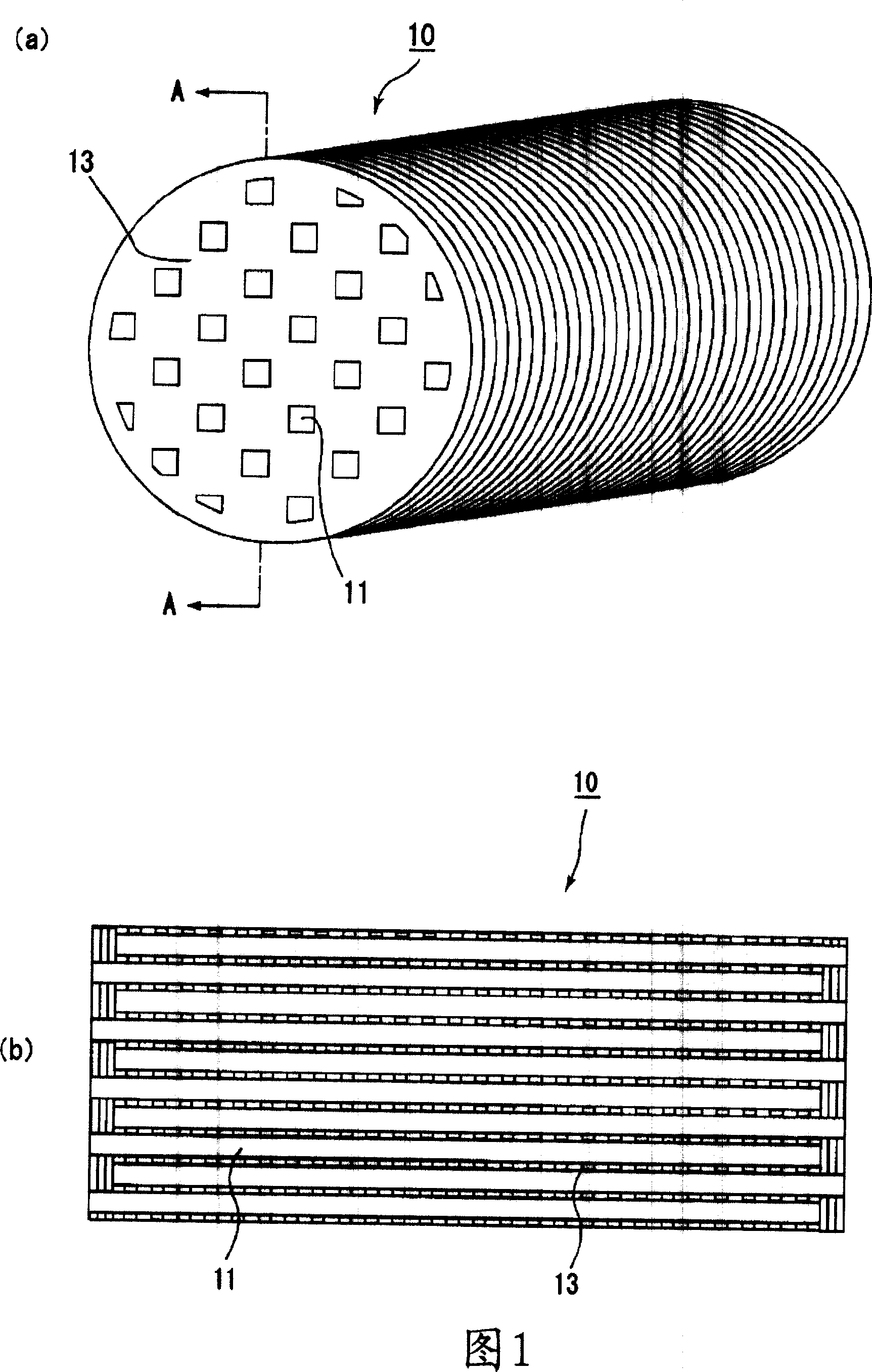
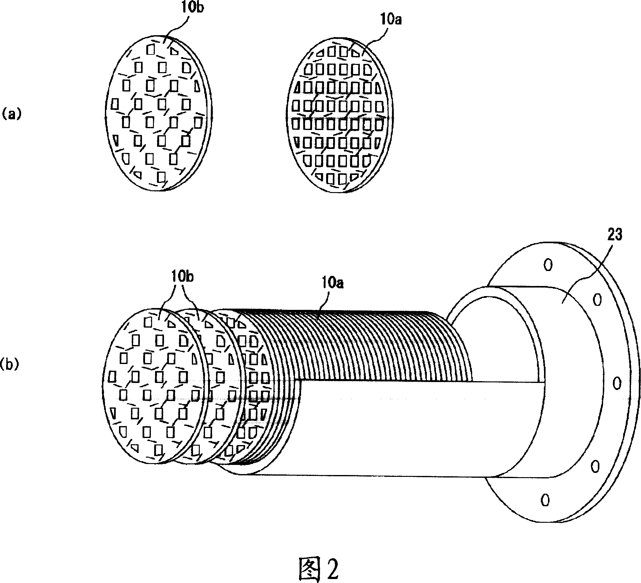
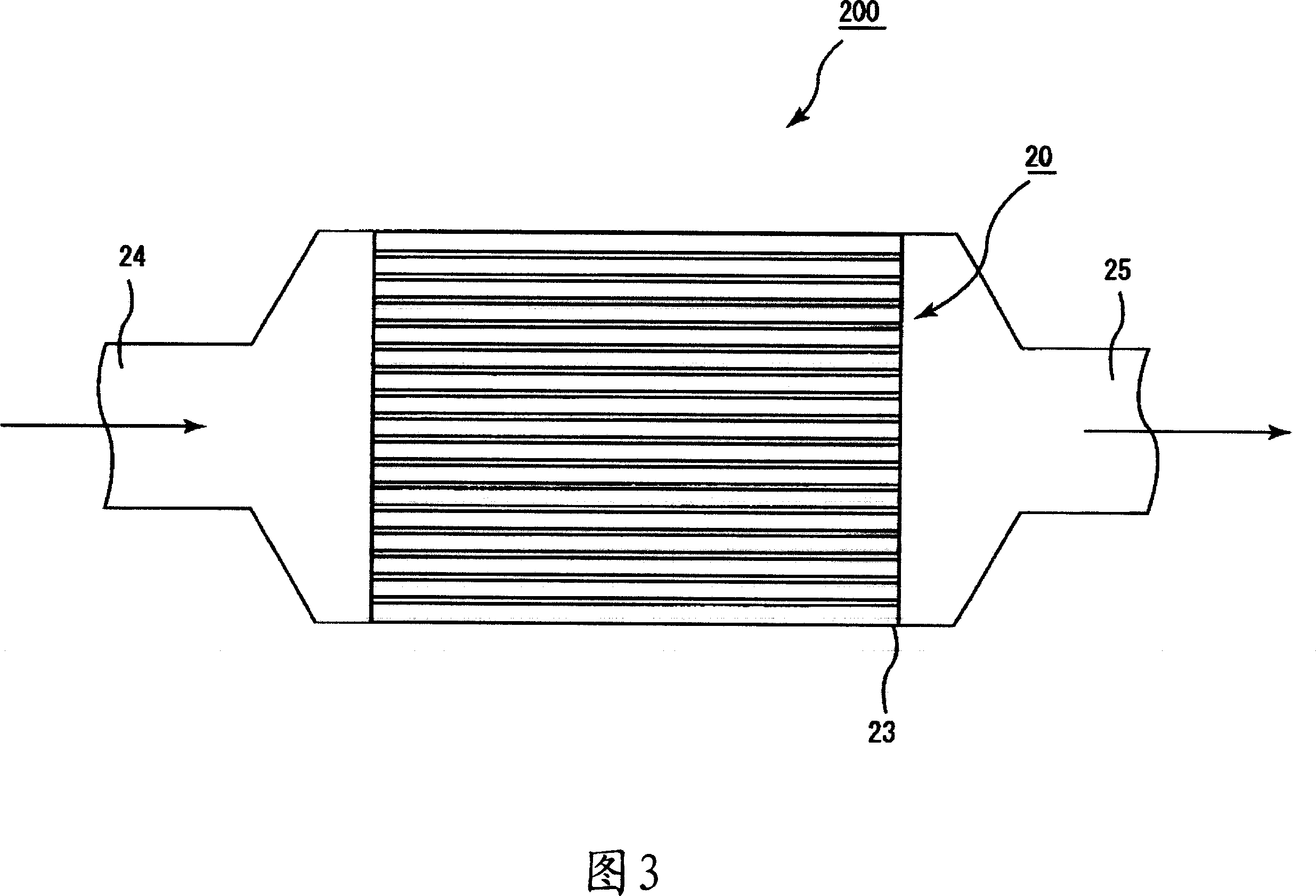
Honeycomb structure body
A structure, honeycomb technology, applied in the direction of dispersed particle filtration, filtration separation, mechanical equipment, etc., can solve the problems of limited installation space, filter crack damage, difficult to make filters into complex shapes, etc., to reduce pressure loss , The effect of increasing the purification function and suppressing the pressure loss
- Summary
- Abstract
- Description
- Claims
- Application Information
AI Technical Summary
Problems solved by technology
Method used
Image

Examples
preparation example Construction
[0119] (2) The preparation process of slurry for papermaking
[0120] Next, the catalyst-loaded inorganic fibers obtained from the process (1) are dispersed in a ratio of 5 g to 100 g in 1 liter of water, and in addition, 10 to 40 parts by weight such as silica Inorganic binders such as sol and 1 to 10 parts by weight of organic binders such as acrylic emulsion, and a small amount of coagulants such as aluminum sulfate and coagulants such as polyacrylamide are added as needed, and fully stirred to prepare Preparation of slurry.
[0121] Examples of organic binders include methyl cellulose, carboxymethyl cellulose, hydroxyethyl cellulose, polyethylene glycol, phenolic resin, epoxy resin, polyvinyl alcohol, and styrene butadiene rubber. Wait.
[0122] (3) copying process
[0123] The slurry obtained in the process (2) is prepared by using a perforated screen in which holes having a predetermined shape are formed at predetermined intervals from each other, and the obtained slu...
Embodiment 1
[0135] (1) Process of applying catalyst to inorganic fibers
[0136] Alumina fibers (average fiber diameter: 5 μm, average fiber length: 0.3 mm) were immersed in an alumina slurry (Pt concentration: 5% by weight) loaded with Pt or the like for 2 minutes, and then heated at 500° C. to prepare adhering Alumina fibers for catalysts. The deposition amount of Pt was 0.24g / 10g alumina.
[0137] (2) The preparation process of slurry for papermaking
[0138] Next, the inorganic fibers obtained from the process (1) were dispersed in a ratio of 1 liter of water 10 g, in addition, as an inorganic binder, 5% by weight of silica sol relative to the fiber was added; as an organic binder, Add 3% by weight acrylic emulsion. Furthermore, a small amount of aluminum sulfate serving as a coagulant and polyacrylamide serving as a coagulant were also added thereto, and the mixture was sufficiently stirred to prepare a slurry for papermaking.
[0139] (3) copying process
[0140] The slurry obt...
Embodiment 2 and 3
[0146] The same procedure as in Example 1 was performed to obtain a honeycomb structure, except that the attached amount of the Pt catalyst was changed to 0.1 g / 10 g alumina (Example 2) and 0.15 g / 10 g alumina (Example 3). The Pt adhesion amount of the honeycomb structure of Example 2 was 2 g / l, and the Pt adhesion amount of the honeycomb structure of Example 3 was 3 g / l.
PUM
| Property | Measurement | Unit |
|---|---|---|
| thickness | aaaaa | aaaaa |
| diameter | aaaaa | aaaaa |
| diameter | aaaaa | aaaaa |
Abstract
Description
Claims
Application Information