
Method for manufacturing brake disk mounted on axis

A manufacturing method and technology of brake discs, applied in the direction of brake discs, friction linings, mechanical equipment, etc., can solve the problems of difficult machining, easy deformation, long cycle, etc., and achieve good friction and wear performance and braking power Large and stable coefficient of friction

Inactive Publication Date: 2007-10-31
湘潭高耐合金制造股份有限公司
View PDF0 Cites 10 Cited by
  • Summary
  • Abstract
  • Description
  • Claims
  • Application Information

AI Technical Summary

Problems solved by technology

[0008] 6. Technical problems in mechanical processing. Alloy steel shaft-mounted brake discs have high strength and high hardness after heat treatment, and the technical requirements, shape and position tolerances, and surface roughness of the products have high requirements. Due to the special heat treatment process, the heat treatment cycle is longer, and it is easy to deform. It requires sufficient finishing allowance, and machining is very difficult.

Method used


Image

  • Method for manufacturing brake disk mounted on axis
  • Method for manufacturing brake disk mounted on axis

Examples


Embodiment 1

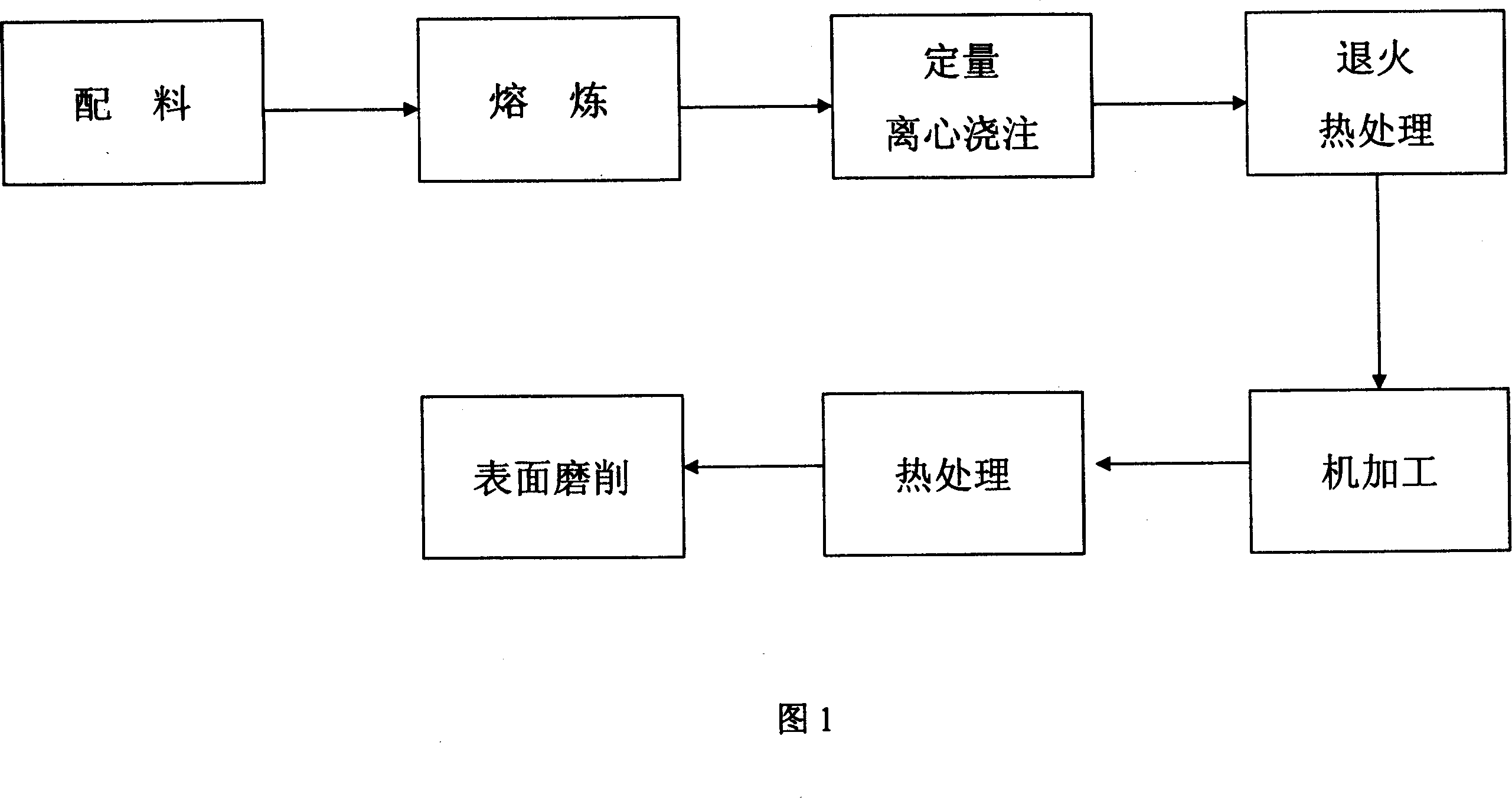
[0042] A ingredient

[0043]Take the materials used in the production of shaft-mounted brake discs for backup, including 1.167 kg of chromium, 0.666 kg of manganese, 0.615 kg of molybdenum, 0.333 kg of silicon, 1.24 kg of nickel, 0.187 kg of copper and 100 kg of industrial pure iron. Carbon, sulfur, and phosphorus are three elements, so there is no need to add the above three elements, and it can be calculated that the above materials contain 0.187 kg of carbon, 0.024 kg of sulfur, and 0.031 kg of phosphorus;

[0044] B melting

[0045] According to the above ratio, put the industrial pure iron into the intermediate frequency furnace for smelting. After the industrial pure iron is melted, perform the first deoxidation treatment at a steel temperature of 1550°C for 21 minutes; then add copper, chromium, nickel, Molybdenum element, conduct the second deoxidation treatment for 31 minutes; then add manganese and silicon for the third deoxidation treatment, when the slag material ...

Embodiment 2

[0053] A ingredient

[0054] Take the materials used in the production of shaft-mounted brake discs for backup, of which

[0055] Chromium Cr is 0.01042~0.01354:1, Manganese Mn is 0.00521~0.01042:1, Molybdenum Mo is 0.00521~0.00729:1, Silicon Si is 0.00313~0.00625:1, Nickel Ni is 0.00937~0.01354:1, Copper Cu is 0.00104~ 0.00208:1, carbon C is 0.00156~0.00261:1, sulfur S is 0.00021~0.00026:1, phosphorus P is 0.00026~0.00035:1;

[0056] 1.2 kg of chromium, 0.614 kg of manganese, 0.7 kg of molybdenum, 0.5 kg of silicon, 1 kg of nickel, 0.2 kg of copper and 100 kg of industrial pure iron. Since the above raw materials contain three elements of carbon, sulfur and phosphorus in different procedures, no need Add the above three additionally, and it can be calculated that the above materials contain 0.15 kg of carbon, 0.02 kg of sulfur, and 0.03 kg of phosphorus;

[0057] B melting

[0058] According to the above ratio, put the industrial pure iron into the intermediate frequency f...


PUM


Abstract

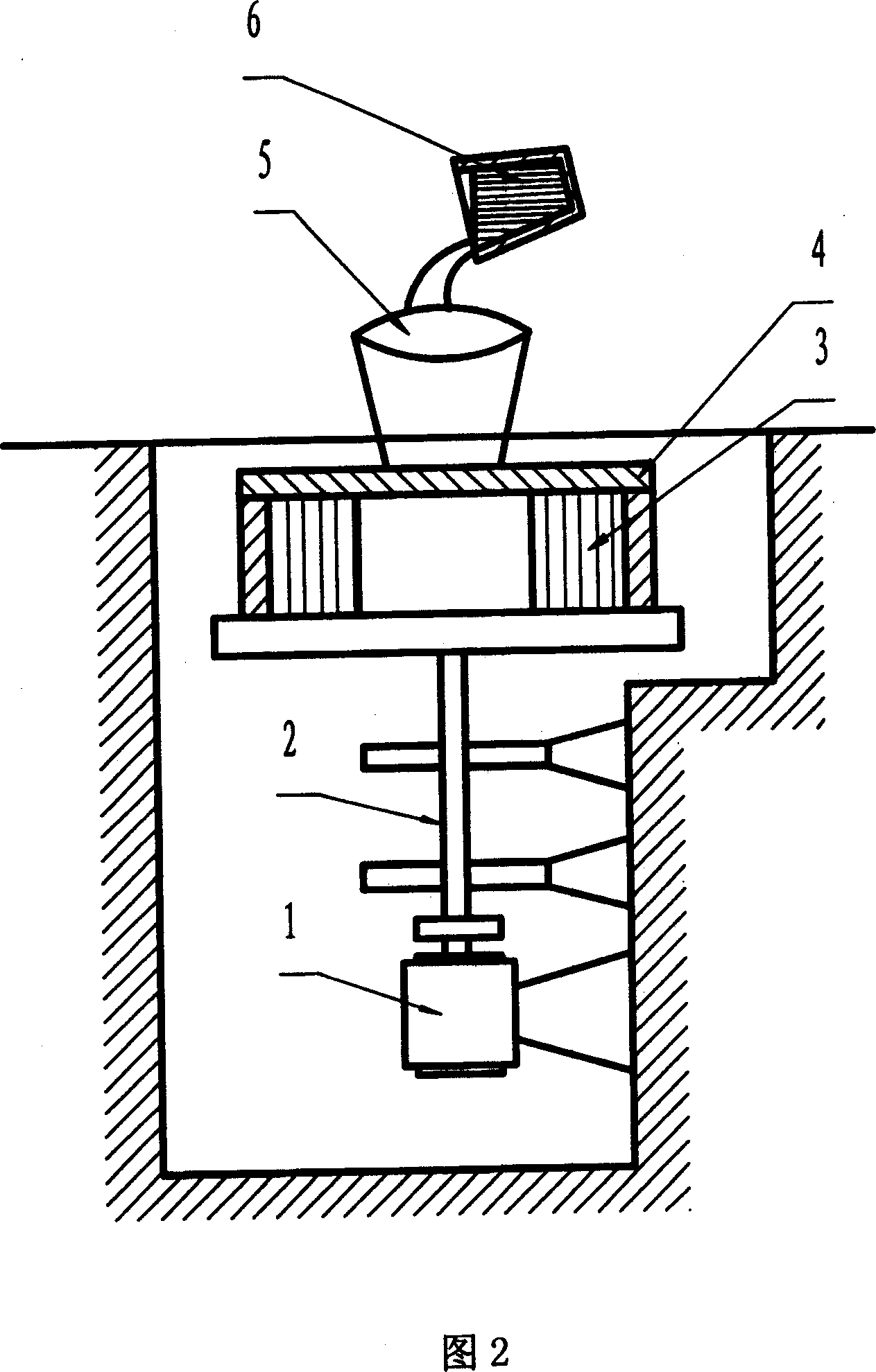
The invention relates to a manufacturing method of brake disk arranged on the shaft, comprising batching, smelting, pouring, annealing treatment, after treatment or the like, the brake disk manufactured can meet the need of motor cars, locomotives and automobiles of 50km / h-160km / h, which has the advantages that the invention has great brake power and is applicable to the high-velocity or high-duty locomotives with better high-temperature mechanic property and heat fatigue durability, good frictional dissipation property, stable frictional factor and smooth braking with greatly improved processing performance of the structure.

Description

technical field [0001] The invention relates to a brake device used by a high-speed train, in particular to a method for manufacturing a shaft-mounted brake disc. Background technique [0002] At present, the brake devices used in high-speed trains are required to have the characteristics of high braking power, reliable performance, good thermal fatigue performance, and good friction performance. The key component of the brake device is the alloy steel shaft-mounted brake disc, which is particularly important. , because the brake disc must have high strength, high temperature resistance, high tissue density and good friction and wear performance, its technical requirements are very high, mainly reflected in the following aspects: [0003] 1. The material composition of the steel plate is complex, there are many alloys, and the content requirements of various alloys are very strict, it is difficult to control and master during the alloy melting process, and there is no releva...

Claims


Application Information

Patent Timeline
IPC IPC(8): F16D65/12F16D69/02B22D13/00
Inventor 赵建向昌武
Owner 湘潭高耐合金制造股份有限公司
Learn More