Ytterbium-bismuth co-doped phosphonate based optical glass and method for making same

An optical glass and phosphate technology, applied in the field of optical glass, can solve the problems of inability to obtain strong luminescence performance and gain effect, and achieve the effects of strong near-infrared fluorescence emission and simple preparation process

Inactive Publication Date: 2008-02-06
SHANGHAI INST OF OPTICS & FINE MECHANICS CHINESE ACAD OF SCI
View PDF0 Cites 30 Cited by
  • Summary
  • Abstract
  • Description
  • Claims
  • Application Information

AI Technical Summary

Problems solved by technology

And they mainly rely on the 808nm pump source for excitation, and cannot obta

Method used


Image

  • Ytterbium-bismuth co-doped phosphonate based optical glass and method for making same
  • Ytterbium-bismuth co-doped phosphonate based optical glass and method for making same
  • Ytterbium-bismuth co-doped phosphonate based optical glass and method for making same

Examples


Embodiment 1

[0058] The preparation method of embodiment 1 is as follows:

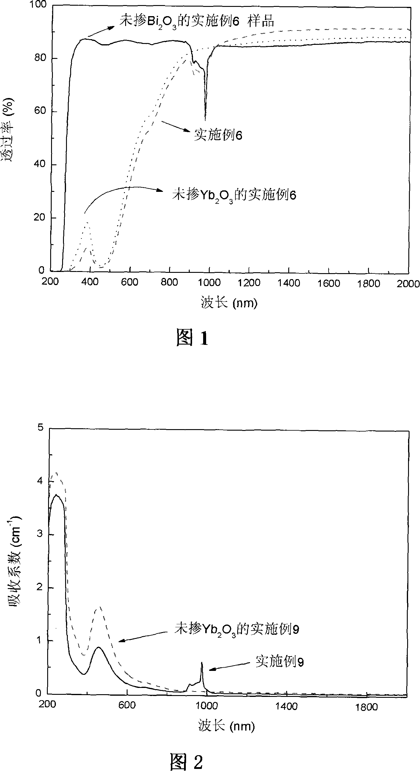
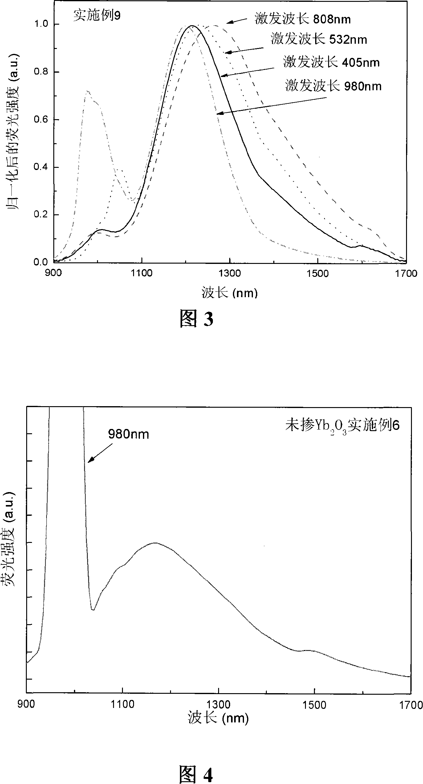
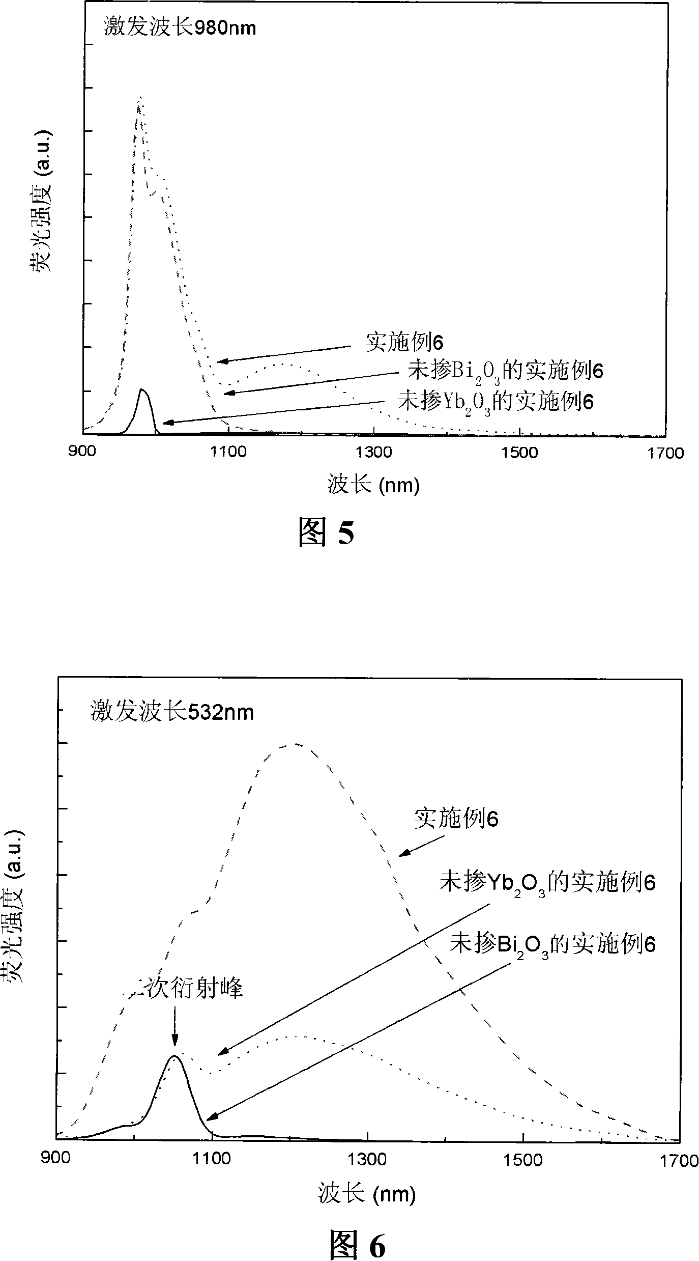
[0059] Select analytically pure raw materials, weigh a total of 20 g of glass raw materials according to the proportion (mol%) of the first example in Table 1, grind and mix them uniformly in a mortar. And pre-fired at low temperature to release the moisture and useless gas components in the raw materials. After the raw materials are fully fired, grind again evenly, and melt in the air at 1400-1550°C, the raw materials are completely melted, homogenized, and clarified into glass liquid. Cool the melt down to a suitable viscosity, and pour it into a preheated grinding tool. After the sample was annealed at 500-600°C for 6 hours, it was cooled to room temperature with the furnace after the power was turned off. After the sample is polished, obvious absorption peaks can be observed around 455nm, 700nm and 980nm, and can generate infrared fluorescence emission across 1000-1600nm under different pump light excitation,...

Embodiment 2

[0060] The preparation method of embodiment 2 is as follows:

[0061] Select analytically pure raw materials, weigh a total of 20 g of glass raw materials according to the proportion (mol%) of the second example in Table 1, grind and mix them uniformly in a mortar. And pre-fired at low temperature to release the moisture and useless gas components in the raw materials. After the raw materials are fully fired, they are ground again evenly, and melted in a weak reducing atmosphere at 1400-1550°C. The reducing atmosphere is achieved by introducing stone mill powder. The raw materials are completely melted and homogenized to clarify into a glass liquid. Cool the melt down to a suitable viscosity, and pour it into a preheated grinding tool. After the sample was annealed at 400-500°C for 6 hours, it was cooled to room temperature with the furnace after the power was turned off. Obvious absorption peaks can be observed around 455nm, 700nm and 980nm, and can generate infrared fluore...

Embodiment 3-5 and 8

[0062] The preparation method of embodiment 3-5 and 8 is as follows:

[0063] Select analytically pure raw materials, according to the ratio (mol%) of No. 3-5 and No. 8 examples in Table 1, respectively weigh a total of 20g of glass raw materials, grind and mix them uniformly in a mortar. The sample was prepared with reference to the method of Preparation Example 1. Obvious absorption peaks can be observed in the sample near 455nm, 700nm and 980nm, and can generate infrared fluorescence emission across 1000-1600nm under different pump light excitations. It has longer fluorescence and longer fluorescence lifetime (as shown in Table 1 and Table 4).


PUM


Abstract

The invention relates t a phosphate base optical glass mixed with ytterbium and bismuth and a manufacturing method of the phosphate base optical glass. The compositions and mol percentage of the glass is that: P2O5(50-80), Al2O3(5-30), Ta2O3(0-5), Ga2O3(0-5), Y2O3(0-5) , Li2O(0-30), Na2O(0-15), K2O(0-5), ZnO(0-15), MgO(0-40), CaO(0-30), SrO(0-15), BaO(0-15), TiO2(0-5), ZrO2(0-5), SiO2(0-20), Bi2O3(0.01-5), Yb2O3(0.01-15); wherein the figures in the bracket refer to the selection range of mol percentage of the corresponding oxide of the compositions. Under the pump of 405nm, 532nm, 808nm and 980nm, higher near infrared ultra wideband fluorescence can be obtained; and under the pump of 980nm, the glass fluorescence emission has a remarkable reinforced effect and is hopeful to be applied in fields such as optical amplifier, superpower laser and tunable laser.

Description

technical field [0001] The invention relates to optical glass, in particular to a phosphate-based optical glass co-doped with bismuth and ytterbium. Ytterbium ions can efficiently absorb pump light of certain specific wavelengths, and realize near-infrared fluorescence of bismuth ions through energy transfer of ytterbium and bismuth Significant enhancement of emission. The glass can emit strong fluorescence in the near-infrared communication band, has long fluorescence lifetime and wide bandwidth, and is suitable as a gain medium for optical amplifiers or lasers. This method can be used to enhance the luminescence of bismuth ions in all bismuth-doped glasses. Background technique [0002] Since the erbium-doped fiber amplifier (EDFA) was developed from the late 1980s to the early 1990s and applied to the optical fiber communication system in the 1.55μm frequency band, it has greatly promoted the development of optical fiber communication to the direction of all-optical tran...

Claims


Application Information

Patent Timeline
IPC IPC(8): C03C3/21C03C3/062
Inventor 阮健邱建荣陈丹平吴伯涛乔延波
Owner SHANGHAI INST OF OPTICS & FINE MECHANICS CHINESE ACAD OF SCI
Why Eureka
Try Eureka