Eureka AIR delivers breakthrough ideas for toughest innovation challenges, trusted by R&D personnel around the world.

Method for inspecting translucent article

An inspection method and technology of light transmittance, which is applied to the original parts used for photomechanical processing, optics, glass molding, etc., can solve the problems of reduced copying accuracy, reduced transmittance, optical unevenness, etc., to prevent surface damage Damage, damage prevention effect

Active Publication Date: 2012-02-15
HOYA CORP
View PDF3 Cites 0 Cited by
  • Summary
  • Abstract
  • Description
  • Claims
  • Application Information

AI Technical Summary

Problems solved by technology

[0008] Even if it is a light-transmitting substrate (such as a synthetic quartz glass substrate), a light-transmitting substrate for a mask blank (such as a glass Substrate) for the exposure mask manufactured, when using the ArF excimer laser as the exposure light to copy the pattern of the mask pattern of the exposure mask on the semiconductor substrate, it also occurs due to the light-transmitting substrate described later. Causes reproduction pattern defects, thereby sometimes reducing the reproduction accuracy
In addition, optical components such as lenses used in the exposure device are also similar to the above, and when the pattern is transferred, defects in the transferred pattern due to the optical parts may occur, and the transfer accuracy may decrease.
[0009] The reason for this is considered to be as follows. When visible light lasers such as He-Ne lasers are used as inspection light, optical changes such as scattering do not occur, but high-energy light such as ArF excimer lasers or F2 excimer lasers is used as exposure light. Optical inhomogeneity (such as caused by local veins, content, foreign matter) that changes local (or partial) optical characteristics (for example, reduces transmittance, changes phase difference) when performing actual pattern replication internal defects) exist in light-transmitting substrates or optical components

Method used


Image

  • Method for inspecting translucent article
  • Method for inspecting translucent article
  • Method for inspecting translucent article

Examples


Embodiment 1

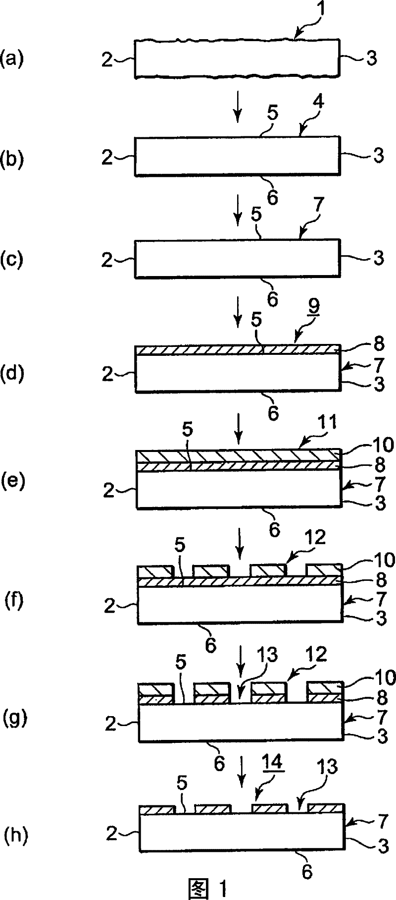
[0177] Prepare 10 synthetic quartz glass substrates in which a synthetic quartz glass base material (synthetic quartz glass blank) produced from silicon tetrachloride etc. The synthetic quartz glass plate obtained in mm was subjected to shape processing and chamfering processing, and an ArF excimer laser (wavelength: 193 nm) as inspection light was introduced into the end face (the side perpendicular to the main surface on which the thin film was formed, and between the main surface and the main surface) The surface roughness of the chamfered face formed between the side faces) is 0.5 μm or less at the maximum height Rmax. In addition, since the main surface of the prepared synthetic quartz glass substrate was not mirror-polished or precision-polished, it was frosted glass.

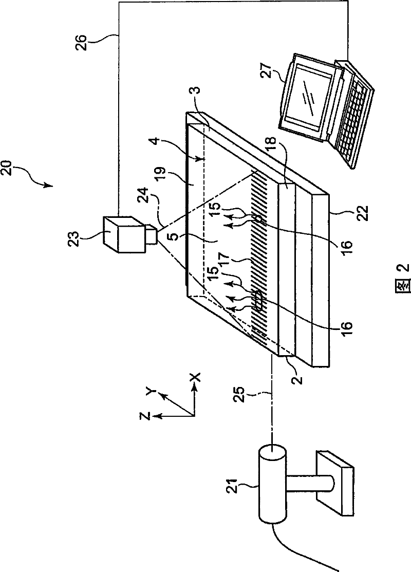
[0178] Next, using the defect inspection device described in the above-mentioned embodiment, a beam shape larger than the thickness of the synthetic quartz glass substrate is introduced into the end surfa...

Embodiment 2

[0192] In the above-mentioned Example 1, inspection of internal defects used a defect inspection device installed in an atmosphere of clean air circulation (ISO class 4, using a chemical filter) to inspect internal defects of synthetic quartz glass substrates, and in addition, with The inspection method of the synthetic quartz glass substrate was carried out in the same manner as in Example 1 above, and the main surface was further precisely polished to obtain a glass substrate for a mask blank. As a result, it is possible to inspect the internal defects of the synthetic quartz glass substrate without damaging the end face to which the ArF excimer laser is introduced, and to select a synthetic quartz glass substrate in which light is not locally generated as fluorescence. Using the selected synthetic quartz glass substrate, the main surface was precisely ground to produce a glass substrate for a mask blank, and further, a halftone phase shift mask and a photomask were produced,...

Embodiment 3

[0194] In the above-mentioned Example 1, the introduction surface where the ArF excimer laser needs to be introduced is formed on the synthetic quartz glass base material (synthetic quartz glass blank) produced by using silicon tetrachloride or the like as a starting material, and ArF is introduced from the introduction surface. Excimer laser, which inspects internal defects inside the base material of synthetic quartz glass. In addition, the introduction surface is formed by partially mirror-polishing the surface of the synthetic silica glass base material so that the size is larger than the beam shape of the ArF excimer laser beam and becomes a mirror state.

[0195] When ArF excimer laser light was introduced into a synthetic quartz glass base material, a region not locally generated as fluorescence was specified, and an exposure device using ArF excimer laser light as exposure light was produced from a block of synthetic quartz glass cut into only the specific region (step ...


PUM

PropertyMeasurementUnit
wavelengthaaaaaaaaaa

Abstract

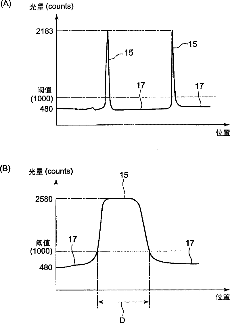
A light-transmitting object examining method enables an accurate examination whether optical nonuniformity is present or not inside a light-transmitting object. The light-transmitting object examining method examines whether nonuniformity (specifically an internal defect (16)) causing an optical characteristic to an exposure light to change locally or at local portion is present or not inside a light-transmitting object (4) that is made of a light-transmitting material and used for photolithography. An examining light having a wavelength of less than 200 nm is made to enter the light-transmitting object and a light (15) having a wavelength longer than that of the examining light and emitted locally or at a local portion is sensed in an optical path along which the examining light propagates inside the light-transmitting object, thus presence / absence of an optical nonuniformity of a light-transmitting object is examined.

Description

technical field [0001] The present invention relates to inspecting the interior of a light-transmitting article made of a light-transmitting material having a light-transmitting property with respect to light having a very powerful energy such as an ArF excimer laser or an F2 excimer laser, for example. Method for inspecting light-transmitting articles with partial variation in optical characteristics, method and apparatus for inspecting glass substrates, manufacturing glass substrates for mask blanks after inspecting internal defects of glass substrates and manufacturing glass substrates for mask blanks A method, a method of manufacturing a mask blank using the glass substrate for mask blanks, a method of manufacturing an exposure mask using the mask blank, and a method of manufacturing a semiconductor device using the mask blank. Background technique [0002] In recent years, due to the miniaturization of patterns formed on semiconductor devices, the exposure light used in...

Claims


Application Information

Patent Timeline
Patent Type & Authority Patents(China)
IPC IPC(8): G01N21/958G03F1/84G03F1/76C03B20/00G03F1/00
CPCG01N21/958G03F1/84C03B20/00G01N21/896
Inventor 田边胜
Owner HOYA CORP
Why Eureka
Eureka Blog
Learn More