Cladding gain guided microstructure hollow optical fiber

A hollow-core optical fiber and microstructure technology, applied in clad optical fiber, multi-layer core/clad optical fiber, optical waveguide and light guide, etc., can solve problems such as development constraints

Inactive Publication Date: 2008-02-13
SHANGHAI INST OF OPTICS & FINE MECHANICS CHINESE ACAD OF SCI
View PDF0 Cites 17 Cited by
  • Summary
  • Abstract
  • Description
  • Claims
  • Application Information

AI Technical Summary

Problems solved by technology

The laser damage threshold of materials such as quartz is much lower than that of air, so the hollow-core microstructured fiber has incomparable advantage

Method used


Image

  • Cladding gain guided microstructure hollow optical fiber
  • Cladding gain guided microstructure hollow optical fiber
  • Cladding gain guided microstructure hollow optical fiber

Examples


Embodiment 1

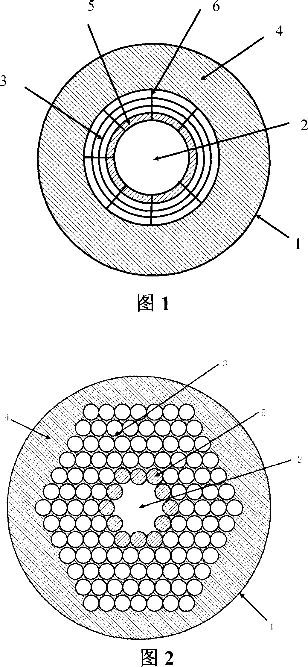
[0024] FIG. 1 is a schematic cross-sectional view of an optical fiber according to Embodiment 1 of the present invention. This is a microstructured hollow-core fiber whose inner cladding region 3 has a spider web-like refractive index distribution. This microstructured fiber is made by covering the inner cladding region 3 on the core region 2 and covering the outer cladding region 4 on the inner cladding region 3. become. The core area 2 is a hollow core with a diameter of 10 μm. Between the core area 2 and the outer cladding area 4 is an inner cladding area 3. The inner cladding area 3 has a refractive index distribution similar to a spider web, and the thickness of the support bar 6 is 0.25 μm, the material is quartz glass, the thickness of the air gap between the support bars 6 is 5 μm, and the material of the outer cladding region 4 is quartz glass. Inject the solution of Rhodamine 6G and ethylene glycol into the air gap 5 in the inner cladding region 3 closest to the cor...

Embodiment 2

[0026] The difference between embodiment 2 and embodiment 1 is: in the air gap 5 in the inner cladding region 3 closest to the fiber core region 2, inject a solution with the dye DCM as a solute, the solvent adopts benzyl alcohol and ethylene glycol, and the concentration of the solution is for 10 -2 mol / L, both ends of the fiber are encapsulated.

Embodiment 3

[0028] The difference between embodiment 3 and embodiment 1 is: the air gap 5 in the inner cladding region 3 closest to the core region 2 is injected with odd red (Kiton red, C 27 H 30 N 2 O 7 S 2 ) is the solution of the solute, the solvent adopts ethylene glycol and glycerol, and the concentration of the solution is 10 -2 mol / L, both ends of the fiber are encapsulated.


PUM

PropertyMeasurementUnit
Thicknessaaaaaaaaaa
Outer diameteraaaaaaaaaa
The inside diameter ofaaaaaaaaaa

Abstract

An air-cored fiber of cladding gain guided microstructure includes a core area and a cladding area. The invention is characterized in that the core area is air-cored and is filled with air; the cladding area includes an internal cladding area and an external cladding area; the cladding area surrounds the core area; the internal cladding area introduces laser materials and the external cladding area is made of solid materials with evenly distributed refractive index; the thickness of the solid material between the hollow core area and a first air hole in the internal cladding area or the air gap is smaller than one wavelength. The fiber is provided with a great model area. The fiber laser adopting such fiber is more conducive to the realization of high power, in addition to the advantages of high gain, high conversion efficiency, low threshold value, good quality of output beam, simple structure and high reliability.

Description

technical field [0001] The invention relates to an optical fiber, in particular to a cladding gain-guiding microstructure hollow-core optical fiber. Background technique [0002] High-power fiber lasers have been increasingly widely used in laser processing, laser medical treatment, laser radar, laser ranging and many other aspects due to their excellent performance and value-for-money price. Under the same output power, fiber lasers have advantages in beam quality, reliability and volume. In addition, due to the reduction of fiber costs and the ease of mass production in assembly lines, this not only arouses the interest of scientists, but also attracts the industry. the great attention of experts in the field. [0003] Fiber lasers were first proposed in the 1960s, but progress has been slow until the development and application of low-loss fiber manufacturing technology and semiconductor lasers brought new prospects for fiber lasers. Fiber lasers use doped fibers as the...

Claims


Application Information

Patent Timeline
IPC IPC(8): G02B6/02G02B6/032G02B6/036G02B1/02
Inventor 赵楚军范滇元唐制祥钱列加
Owner SHANGHAI INST OF OPTICS & FINE MECHANICS CHINESE ACAD OF SCI
Why Eureka
Try Eureka