Method and device for manufacturing optical cable connector metal lock pin

A technology for optical fiber connectors and manufacturing methods, which is applied in the field of manufacturing and installation of metal ferrules for optical fiber connectors, can solve problems such as difficult production, large equipment loss, and inability to weld, and achieves a high degree of automatic control and stable electroforming parameters , the effect of uniform metal layer

Inactive Publication Date: 2008-02-20
宁波航中智能电器有限公司
View PDF1 Cites 4 Cited by
  • Summary
  • Abstract
  • Description
  • Claims
  • Application Information

AI Technical Summary

Problems solved by technology

[0002] Optical fiber connector is an indispensable component in the optical communication network system. The hollow ferrule is its core component and has high technical requirements. Generally, the blank is manufactured first, and then the outer circumference and inner hole of the blank are finished to make it meet Requirements for inner and outer diameters and concentricity, and the outer diameter of the optical fiber is only 0.125mm, which requires the fiber ferrule to match, so the inner and outer diameters are very small, so the production is difficult; at present, zirconia ceramic ferrules are commonly used in China , the main production place is in Japan. So far, Shanghai, Shenzhen and other places have also concentrated some ferrule finishing manufacturers, but most of their blanks are provided by foreign countries; therefore, the research and development and production of ferrule blanks have become domestic fiber optic connectors One of the bottlenecks of industrial development; ceramic ferrule blanks are made of specially treated high-purity zirconia powder raw materials, granulated and then injected into special molds, and sintered into blanks at a high temperature of 1200°C, resulting in high energy consumption and equipment loss Large; and the zirconia ceramic ferrule has the disadvantages of being fragile, unable to be miniaturized, and cannot be welded; for this reason, people have begun to develop and produce metal ferrules. At present, there are many manufacturing schemes for metal ferrules, such as the invention patent authorized by our country " Metal ferrule manufacturing method and its manufacturing device", authorization number CN1259458C, its manufacturing method is that a plurality of core wire holders for holding the core wires are arranged and held in a circumferential shape, and the periphery of the holder is set There are multiple jigs equipped with metal used for electroforming, and while the core wire frame is rotated, the holder is rotated to perform electrolysis; this kind of core wire is fixed on a single core wire frame made of pillars, and then the core wire The frame is fixed on the holding fixture, and the core wire frame is rotated while the holder is rotated; that is, it needs to use rotation and revolution, and the structure is complicated; another invention patent published by our country "the method of manufacturing hollow metal components and the electric method for implementing this method Casting equipment", publication number CN1392984A, is to connect the cathode of the power supply at both ends of the metal wire, and connect the anode at both ends of the electrodeposited metal object or the basket containing the electrodeposited metal object, and the core wire holding fixture is placed horizontally on the electroforming tank , the gear is driven by a belt to make it rotate, and it is not explained how to ensure that the two ends of the core wire rotate synchronously; in terms of temperature control, the above two patents directly adjust the temperature in the electroforming tank, and it is difficult to ensure that the electroforming liquid is in the electroforming tank. Constant temperature during the casting process

Method used


Image

  • Method and device for manufacturing optical cable connector metal lock pin

Examples


Embodiment Construction

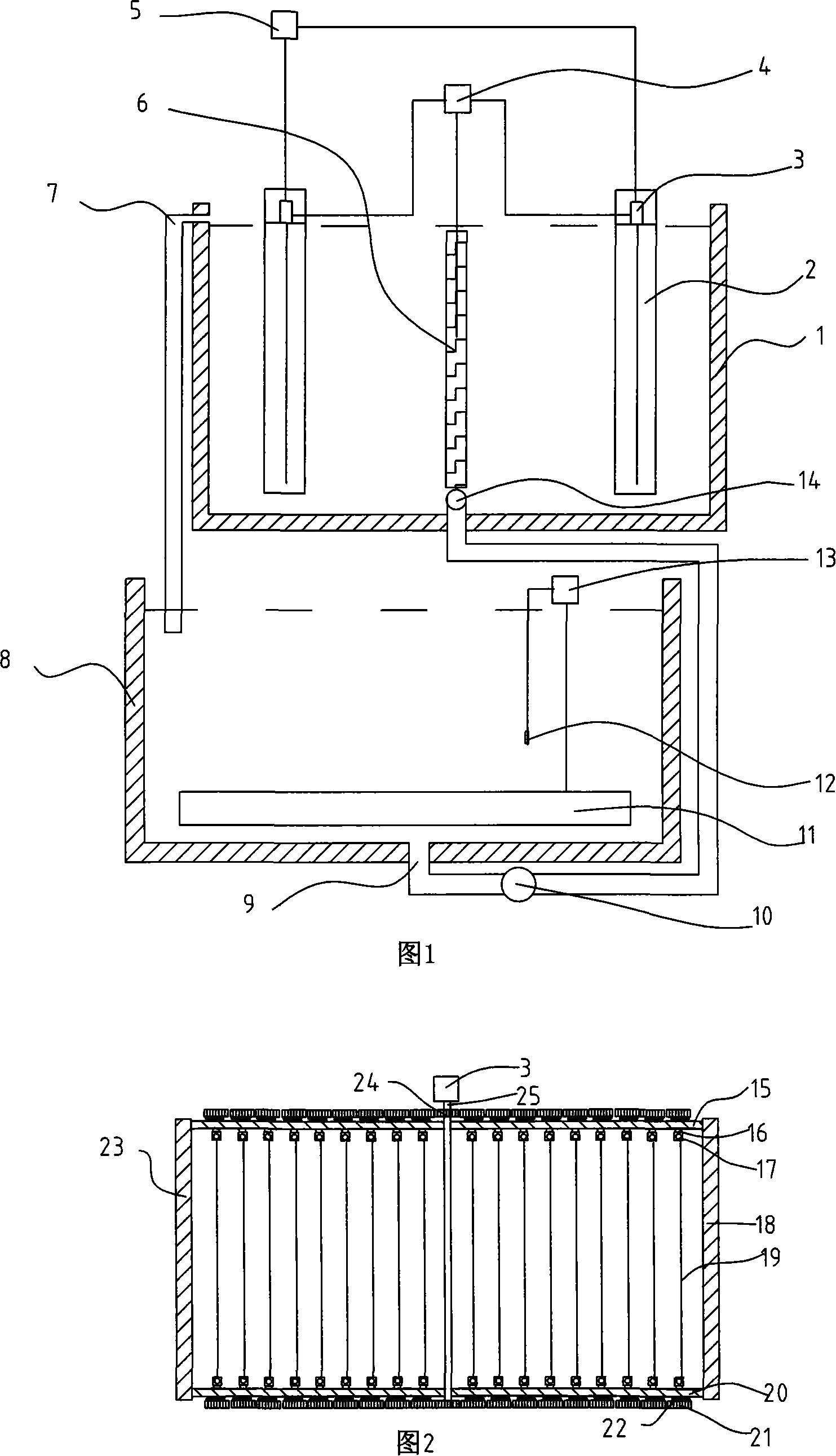
[0022] Referring to Figures 1-2, a method for manufacturing a metal ferrule for an optical fiber connector of the present invention includes the following steps:

[0023] a. install the core wire 19 on the core wire shelf 2;

[0024] b. Degreasing and activating the core wire 19;

[0025] c. Place a titanium metal mesh basket 6 in the middle of the electroforming pool 1, and put metal nickel in the mesh basket; place core wire shelves 2 symmetrically on both sides of the titanium metal mesh basket 6;

[0026] d. The titanium metal mesh basket is connected to the anode of the power supply 4, and the core wire shelves on both sides are respectively connected to the cathode of the power supply 4, forming a single anode and double cathode structure;

[0027] e. Put the electroforming solution in the temperature control tank 8, and control the temperature between 50-60°C;

[0028] f. The electroforming solution in the temperature control tank is automatically pumped into the elec...


PUM


Abstract

The invention discloses a manufacturing method and the device of the metallic inserting core of an optical fiber connector, wherein, the method and the device are used for manufacturing the inserting core of the optical fiber connector used in communication. The invention is respectively provided with the temperature controlling groove with a temperature controlling device and the electric casting groove with a net basket in the middle part. The two sides of the net basket is symmetrically provided with a core cable rack which adopting the structure with single anode while double cathodes. The core cable rack is driven by a single electric motor and a gear wheel as well as a synchronous shaft so as to drive each core cable to rotate. The invention has high automatic control level; the separately arranged electric casting groove and the temperature make electric casting parameters more stable. The structure of the core cable rack symmetrically arranged on the two sides of the titanium made net basket and the structure with single anode while double cathodes make the deposited metallic layer much evener with much higher concentricity. Through the driving operation of the gear wheel and the synchronous shaft, only one electric motor is able to drive all the core cables and the two terminals on the core cable rack to synchronously rotate, ensuring that the two ends of the generated inserting core have the same radius.

Description

technical field [0001] The invention relates to the technical field of electrolysis or electrophoresis production process of coating and the device used, in particular to the electroforming technology for connector ferrule in optical communication. Background technique [0002] Optical fiber connector is an indispensable component in the optical communication network system. The hollow ferrule is its core component and has high technical requirements. Generally, the blank is manufactured first, and then the outer circumference and inner hole of the blank are finished to make it meet Requirements for inner and outer diameters and concentricity, and the outer diameter of the optical fiber is only 0.125mm, which requires the fiber ferrule to match, so the inner and outer diameters are very small, so the production is difficult; at present, zirconia ceramic ferrules are commonly used in China , the main production place is in Japan. So far, Shanghai, Shenzhen and other places ha...

Claims


Application Information

Patent Timeline
Patent Type & Authority Applications(China)
IPC IPC(8): C25D1/02G02B6/42
Inventor 张敏航
Owner 宁波航中智能电器有限公司
Why Eureka
Try Eureka